This thread has been locked.

If you have a related question, please click the "Ask a related question" button in the top right corner. The newly created question will be automatically linked to this question.

TPS543C20: The output is oscillated.

Part Number: TPS543C20
Other Parts Discussed in Thread: , TPS543B20

Hi Expert, 

I got a not stable output with following schematics:

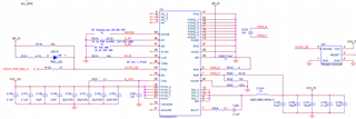
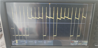
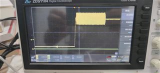
The output seems oscilating all the time. I will attach waveform later. 

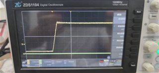
BP has got stable 5V. What's the EN timing?  I saw EN is always low, but the output begin to oscilate.

Thanks

Peter 

  • Hi Peter,

    Please do share the waveforms if possible. I took a look at your design and everything seems fine from the first pass analysis, but looking at the waveform may help further explain. 

    If EN is low, the power stage of the TPS543C20A will be disabled. Is it possible that the noise you are seeing is coming from another part of the system?

    Please see section 8.4.3. of the datasheet regarding the timing and behavior of EN.

    Regards,

    Alec Biesterfeld

  • Hi Alec, 

    The following is output waveform. Sorry for wrong information, EN is about 2V, not low.

    I have disconnected most of the load, 

    Thanks

    Peter

  • Hi Alec,

    This is start up waveform.

    Thanks

    Peter

  • Hi Peter, 

    If EN is left floating, it will be pulled up to BP internally. The waveforms you showed look like the device is current limiting. Based on your Ilim resistor selection, the current limit should be around 34A. Would you be able to capture the SW node by chance during the startup event? Also, I know you mentioned most of the load was removed, but is there any low impedance path to ground the output sees?

    Also, I can take a look at the layout to verify if the routing and component placement may be impacting what you are seeing.

    Sincerely,

    Alec Biesterfeld

  • Hi Alec, 

    The following is output and BST(green) waveform. I measured the output impedance (not powered up), and it's more than 10K. Short to GND shouldn't be the cause. But if you think it's overcurrent, I will check other non-passive components.

    There are only a few supporting components for this chip. I don't know which one i should change for debug.  Is Rramp worth trying from 187K to 51.1K for control loop? or trying connect a electrolytic cap? 

    I will send layout after check.

    Thanks

    Peter

  • Peter,

    I think a few things may be worth looking at in this scenario. I would first examine if a lower ramp setting helps correct the issue (51.1 kohm and 8.66kohm are two options you could look at given the large inductance). I would also try a lower inductor value as our design tools recommend 0.500uH- 1.5uH for this application. Changing the inductor value will likely create a need to change RAMP. Please let me know if this is a feasible option and I can recommend a RAMP value based on the inductor selection.

    A final debug option, that I do not suspect is the issue but is nonetheless something to rule out is pulling out the LED pulled down by PG. This provides a load on BP, which should be sustainable given the rating of the part, but I would like to rule it out as an issue if the RAMP and inductor changes do not succeed in your case.

    Regards,

    Alec Biesterfeld

  • Hi Alec, 

    This 5V is for a daughter. After I added the daugter card, this DC/DC is working well, which means TPS543C20 is not stable under light load or no load. Is there any way to get stable under light load? 

    By the way, two boards using TPS543B20 can boot up under same light load despite there is a short time oscilation.  If there is a daughter card, both C20 and B20 has no oscilation.

    Thanks

    Peter

  • Hi Peter,

    How are your RSP and RSN pins routed? Does the daughter card need to be connected to complete the feedback?

    Regards,

    Alec Biesterfeld

  • No, as you see in the sch, whole required components are local, then provide 5V to the daughter.

    Thanks

    Peter

  • Thank you Peter for the clarification. One additional consideration for this design would be including an RC snubber between SW and GND. I recommend a 1nF cap and a 1-3ohm series resistor. This can help reduce any high frequency voltage overshoots and undershoots given the input of 12V.

  • Alec, 

    Changing the freq from 500K to 1M or adding more 2x 100u Ceramic cap can solve this issue. I close this thread.

    Thank you

    Peter.