


I know, I know, this topic has been discussed before, but I wanted to share some information and possibly get some information back.
I'm currently running this at 120VAC and keeping the 84VDC output, starting with the Eval Board. First, the 90W isn't a hard stop. I was able to get more power and a good looking waveform without changing anything, 150W maybe. I added a leading edge blanking circuit to R23 on the current sense line, though I don't think this did much. My largest improvement seemed to be increasing C18, the filter cap on the VBULK circuit. I had also increased C15, C13, and C7, the caps on LSNS, CS, and VDD respectively. I also increased the inductor to about 170uH and added 2 more 470uF caps on the output. I am now able to get a minimum of 250W with 94% efficiency and 0.956 PF with surprisingly little necessary to keep it cool, just a fan for now.
Summary:
L4 = 170uH
Output caps = 4x 470uH
C7 = 2.67uF
C15 = 1.21uF
C18 = 1.2uF
Leading edge blanking - 0.01uF cap in series with base of MMBT2222 (Base to R19, Collector to CS, and Emitter to GND)
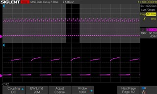
Now here's where I'm having trouble. In the screenshot below, the shaded part is the top of the AC curve as seen at TP11 with ground clip on TP6 (scope is floating anyways). A zoom-in shows that every other pulse has a rounded top versus a sloped top. I have decreased R19 from 1 150R to a 50R resistor, increased C11 to a 1uF, changed R1 to a 100R, and tried a variety of larger caps on VBULK, LSNS, and CS. All to no avail.
Anyone have any ideas? I can't figure out why it's doing this.
