


Hello,
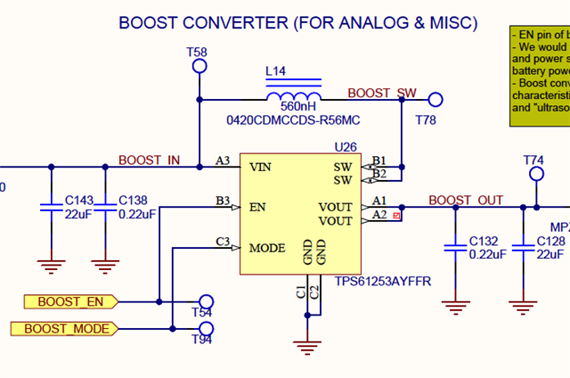
We have a boost design using the TPS61253A; schematic attached. I have one board here which is misbehaving, and I need some advice as to what the cause would be.
1. The input voltage can range from 2.8 to 5.2 V. A good board will output 5 V, and will go into pass-through mode if the input exceeds 5 V.
2. On the failed board the converter doesn't start up if there's a load, even a very light load of tens of milliamps, but it will run under load, even a decent load of 0.5 A, once its output is at 5 V. I've not tried higher loads.
3. The weirdest part is that it's stuck in pass-through mode until the input gets down to about 3.8 V. In other words, as I reduce the input from 5 V to 3.8 V the output tracks the input, and only at 3.8 V and below does the chip start switching and the output goes up to 5 V. The switching waveform looks the same between good and failed boards.
4. Even with the input below 3.8 V, the converter still won't start under load.
5. The chip's Enable input is high, and the Mode input is low (Auto-PFM).
6. Ohmmeter checks don't indicate anything different between a good board and the failed board: no low resistances to ground, no shorts between signals. Since this is a BGA package, I can't access the chip pins directly.
What could be going on here?
Thanks,
Scott
 ,
,

