This thread has been locked.

If you have a related question, please click the "Ask a related question" button in the top right corner. The newly created question will be automatically linked to this question.

TPS54308: How much current at the power-on moment?

Part Number: TPS54308

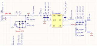
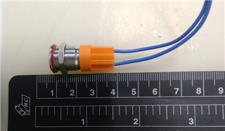
The main schematic is as below ,  P1 ,& P2 is the two pad for me soldering a mechanical bottun. The normal power on current meassured with DMM6500 is  7~9 mA , The question is when I quickly switch the bottun on and off , there will be big probability that the fuse(F1) is burned out.  Is it because there is the big current flow through VIN of TPS54308 at the swtich on moment or something? 

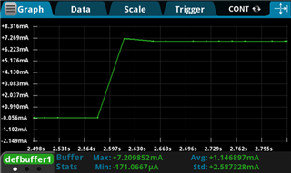
But when I made the F1 in serial connection with DMM6500 to try to measure the peak current , the phenomena is no longer show up again.


  •  

    The most likely problem is that you are connecting a 24V input source to 20uF of ceramic capacitance through only the ferrite bead and fuse, so the current is extremely high for a very short period of time.  With 480uC of charge to be delivered, the current can easily exceed the fusing current on the fuse.  You need to add some inrush control to limit the rise-time of the voltage on the 2x 10uF input capacitors.

    A simple inrush control circuit can be made by adding a series resistor to control the time-constant of the input capacitors, and a P-channel FET in parallel with the resistor to reduce the input impedance and IR drop once the capacitors have been charged.

    I've drawn it with a simple R-C delay circuit to turn on the PFET, but there are other ways ways to turn-on the PFET and bypass the inrush limiting resistor.

    If you're willing to dissipate some power at the input, you could also do a simple N-channel source-follower with an R-C charge circuit on the gate to control the rise-time on the 2x10uF input capacitors to the TPS54308, but list will leave the FET in a linear region, dropping it's Vgs theshold voltage and dissipating some input power.

    You could also consider replacing the Fuse and inrushing limiting with an "E-Fuse" with integrated inrush limiting and/or output slewrate control.  If you're interested in an E-Fuse, check the TPS2663  which has adjustable output soft-start, adjustable current limit, and can be configured for either current limiting or circuit braking.

  • The DMM6500 has a shunt resistance of 10kohm to 5mohm dependent on the current range.   

    So I believe the meters shunt resistance is limiting the inrush current. 

    if you want blow the fuse with the meter in series, try a low resistance external shunt or manually setting the internal shunt resistance to the high current range. 

  • Hi , Peter  Thank you for teaching and giving me the strong advice , I think it would  probably resolve my problem !  

  • Hi , David  Thank you for telling me that shunt resister inside DMM6500 would decrease the inrush current,I had not concerned it.   Next time I will try the other way to measure the inrush current !

  • Hi Martin,

    Thanks for your feedback. We will close this thread first. If you have any question, you can re-open it or create a new thread.

    Thanks,

    Lishuang

  • OK ! Thank you

  •  

    You're welcome.

    In addition to the shunt-resistance that listed, there is a potential issue with the sampling rate of the DMM6500.  While setting the current meter to the 10A range setting and not auto-scale will likely allow the fuse to blow, the DMM6500 would still likely not capture the peak currents of the inrush when in 1kHz sampling mode, because the inrush peak is likely less than 1ms.  In addition to changing the meter's current range, you'll want o increase the sampling rate to it's maximum 50kHz to best capture the inrush waveform.