This thread has been locked.

If you have a related question, please click the "Ask a related question" button in the top right corner. The newly created question will be automatically linked to this question.

Controller for switching a buck converter (or a syncron converter)

Other Parts Discussed in Thread: UCC28051, UCC28501, PMP30446, UCC23313-Q1, UC3823

Hi Team,

We would like to ask your help regarding the customer's inquiry below.

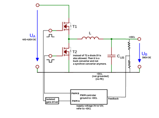
I am looking for a controller for switching a buck converter (or a syncron converter). The input voltage will be 390V to 410V and the output voltage should be 380V. Therefore i will need a driver and an isolation transformer for the gates. But first of all i need a controller. Therefore I am looking for your help to find the right one.

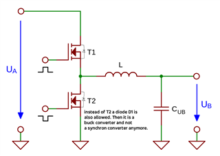
The gates of T1 (and T2) will be connected via an isolated driver to the controller i am looking for.

According to the customer, the supply to the controller could be 3.3V,12V or 24V.

Thank you for your support!

Regards,

Danilo

  • Hi Danilo,

    Please check this E2E thread for some ideas about driving the high-side HV MOSFET. Gate drive transformer may not be possible for such high PWM duty cycle. If you use a diode in place of T2, then a single channel high-side isolated driver could be used to drive the high-side. I also found PMP30446 which is a reference design, close to the specs provided but your design could be simplified because your input voltage is comparatively lower. this design gives a good example of the gate drive for a HV non-sync buck and it is using the UCC28051 PWM controller but really, any single-ended, general purpose, PWM controller can be used.

    Regards,

    Steve M

  • Hi Steve,

    thank you for your great help. Thanks also to Danilo that he repost my inquiry to the E2E forum.

    Do I understand correctly when I use the UCC28501 PWM controller together with UCC21220AD isolated driver the controlling of my non sync buck converter will work (as shown in the PMP30446 design).

    Therefore I have a further question: The DRV output of UCC28501 is connected to the input A and B of UCC21220AD. But I thought that Input A and B should be inverted in order to avoid a short circuit by Q1 and Q4.

    The UCC1845 (as mentioned in the E2E thread you linked) seems to have an undersized voltage isolation.

    Best regards

    Andreas

  • Andreas,

    In the PMP30446 ref design, the two gate drives are switching two, independent, non-synchronous buck converters synchronously. This is not a synchronous buck, as your question seems to imply, where the upper and lower MOSFETs must be switched asynchronously. This is done because of the high input voltage required for this design. Your case will be much simpler since 400V is more manageable. In your case, since you are not using a sync buck, you could use a single channel, isolated gate driver as opposed to the dual channel UCC21220AD. TI has many single channel isolated drivers but something like UCC23313-Q1 would be compatible with VDD=13V (driver has 12.5V UVLO(off)) to the controller and driver. 

    Regards,

    Steve M

  • Hi Steve,

    attached you find the schematic I draw above but add some additional information. We need a voltage controled buck converter (or a sync converter).

    The isolated drivers are a good choice from you but I need the PWM controller with voltage mode too. Current mode is not useful for our situation. UCC28501 seems to have a current mode but not a voltage mode.

    I find the UC3823 which you can change to voltage mode. Is this IC sufficient for the buck converter I want to realize?

    Regards

    Andreas B.

  • Andreas,

    TI general purpose, current mode PWM controllers can be set up for VMC by feeding the RAMP into the CS pin and they are not topology specific so they can be used for flyback, forward, buck, boost, etc. Configuring a CMC for VMC is a feature detailed in our data sheets as shown below. Also, any UCC35xxx is VMC specific (in the part number, the 5 vs the 8, determines CMC vs VMC). UCC35706 is one example of a TI, VMC specific PWM controller. Here is a parametric search result of all TI general purpose PWMs that are either VMC or CMC that can be configured for VMC.

    Other challenges I see in your schematic:

    1. The supply voltage (VCC) to the PWM is specified as 3V-12V. Please pay attention to the UVLO (ON/OFF) of whatever PWM you select because they do not turn-on or operate down to 3.3V.  UCC2813-3 has the lowest UVLO of 4.1 VON/3.6 VOFF but is limited to abs max of 12 V. Hopefully it is not required that you be able to start from such low VCC as 3.3 V.
    2. For a sync buck converter, when you introduce a high-side isolated gate driver, but use direct drive on the low-side SR, there will be a delay mismatch between the high-side and low-side. To avoid possible cross-conduction, you will need to match the gate drive delay between the high-side and low-side. This will include introducing a gate drive delay to the low-side SR. If a diode is used in the low side (non-sync buck), then no problem with your circuit as it is drawn.

    Regards,

    Steve M

  • Good Morning Steve, thank you for your good support and your hints. For me a voltage controlled converter is necessary. Great to read that nearly all PWM controller can be set to this mode. Now I have no more questions. Best regards Andreas B.