This thread has been locked.

If you have a related question, please click the "Ask a related question" button in the top right corner. The newly created question will be automatically linked to this question.

TPS51220A: External resister current sensing for AVE simulation

Part Number: TPS51220A

Hi All,

I found the question.
And my question is same.

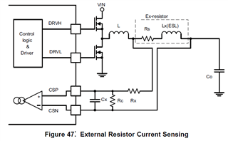
Do you have external resister current sense model for AVE now?

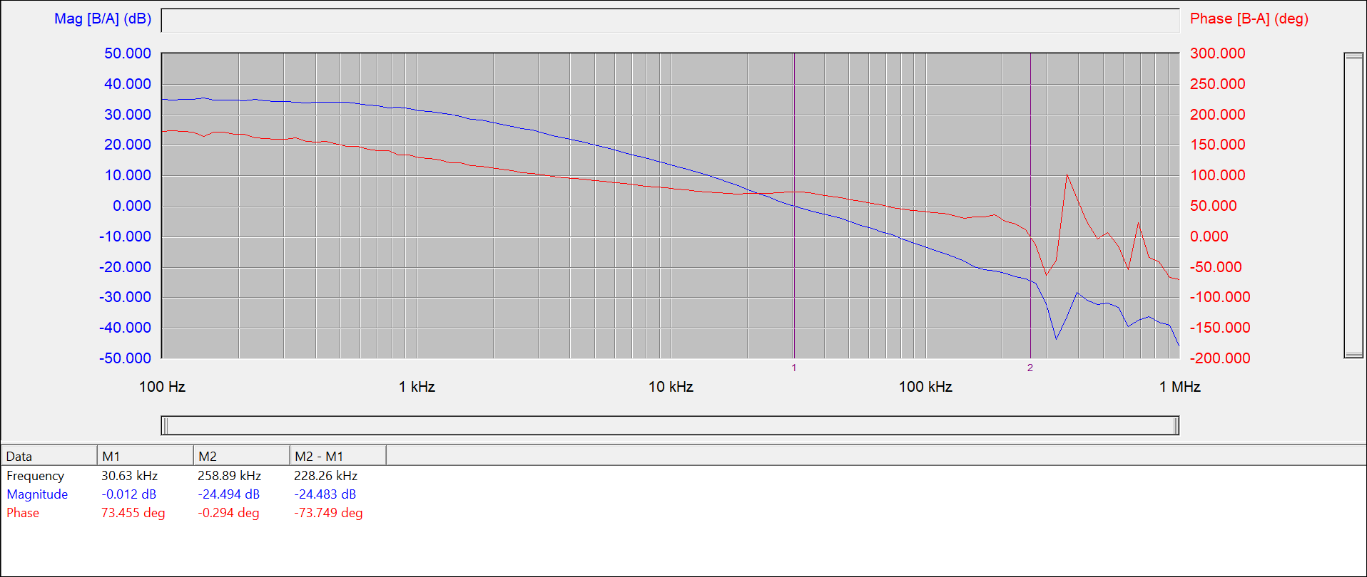
If you don't have it, is there a way to get bode plot of it?

Best Regards,

T.Morimura

  • Hi,

    The Pspice average model can be used to get bode plot. Pspice for TI software is available on Ti.com.

    Thanks,

    Andrew

  • Hi,

    Sorry for misunderstanding your meaning. For the case of using external current sense resistor, I think it can be converted to the condition of using DCR sensing.

    I'll look into it and give you feedback later.

    Thanks,

    Andrew

  • Hi Andrew,

    Thank you for your reply.

    I already have Pspice and slim157a.

    But I think slim157a is DCR current sensing.

    And I couldn't find external resister current sensing AVE model.

    I'd like to get bode plot of external resister current sensing.

    Do you know how to get it?


    Thanks.

    T.Morimura

  • Hi Andrew,

    Thank you for your additional reply.

    I'm looking forward to your feedback.

    Thanks.

    T.Morimura

  • Hi,

    I want to firstly check that: did you use the external resistor current sensing method like Figure 47 on datasheet? Or you didn't add the RC filter and just get the voltage on external resistor in to CSP/CSN?

    Just to make sure that I understood your application correctly.

    Thanks,

    Andrew

  • Hi,

    Yes, I'm going to use Figure 47 method and add RC filter.

    Additionally, I'd like to add Rc resistor like as Figure 49 for external resister current sensing.

    (I'm going to add Rx, Cx and Rc for external resister current sensing.)

    Thanks,

    T.Morimura

  • As mentioned in your original question, we don't have an average current model for the external resistor sensing, but I think I have thought about an idea to convert the external resistor sense circuit into DCR sense circuit.

    For the external resistor sense circuit: if the ESL of external resistor is not considered, the voltage on external resistor equals to IL*Rs, which goes into CSP-CSN. Here IL is the inductor current and Rs is the resistance of external resistor.

    If ESL of external resistor is considered, with the RC filter like figure 47, the voltage goes into CSP-CSN equals to IL*(s*Lx+Rs)/(sCxRx+1). With equation (18), the voltage also equals to IL*Rs.

    Above all, the CSP-CSN voltage with external resistor sense method equals to IL*Rs.

    For the DCR sense method, first we can get the voltage on inductor equals to IL*(sL+DCR). The voltage goes into CSP-CSN equals to IL*(sL+DCR)*(Rs2||1/sCs)/(Rs1+Rs2||1/sCs). Here "||" means to get the parallel impedance. Simplify the equation, we can get the voltage goes into CSP-CSN= IL*(sL+DCR)*Rs2/(Rs1+Rs2+s*Cs*Rs1*Rs2).

    If we want to let the DCR sense model can be equivalent to the external resistor model, just let: Rs1+Rs2=DCR, Cs*Rs1*Rs2=L, Rs2=Rs.

    But the external resistance must be smaller than DCR with this method. And what's the external resistance that you used compared with the DCR?

    Thanks,

    Andrew

  • Hi Andrew,

    Thank you for your reply.
    I'm going to use below parts.

    L:4.7uH, 14.4mohm
    Rs:5mohm

    Rx:10ohm
    Cx:470pF
    Rc:33ohm

    I can't understand your suggestion in detail.
    Which values should I use?
    Thanks,

    T.Morimura

  • Hi,

    Thanks for the provided information.

    In my understanding, I think the value should be as below after translating the parameters into DCR sense model for Pspice:

    Rs2=5mohm. Rs1=13.76mohm. Cs=0.089H.

    L=4.7uH, DCR=14.4mohm.

    But the method to get those values are just based on theoretical analysis. I will have some validation on EVM about this method today and tomorrow to check the accuracy.

    Thanks,

    Andrew

  • Hi Andrew,
    Thank you for the parameters.
    Please let me double check.

    Cs=0.089H is 0.089F, right?

    You will check on EVM the parameters as below, right?


    L:4.7uH, 14.4mohm

    Rs:5mohm

    Rx:10ohm
    Cx:470pF
    Rc:33ohm

    Thanks,
    T.Morimura

  • Yes, it should be 0.089F.

    I want to check on EVM just to verify the method to get equivalent parameters. I'll see if I can find similar components to do the test.

    Thanks,

    Andrew

  • Hi Andrew,
    Thank you for reply.

    >I want to check on EVM just to verify the method to get equivalent parameters. I'll see if I can find similar components to do the test.

    If you are going to use 5mohm and 13.76mohm as Rs* for actual circuit, please be careful because they are too small.

    Thanks,
    T.Morimura

  • Thanks for the remind.

    I'll use external resistor for actual circuit and see if the bode plot can match with the theoretical equivalent DCR simulation result.

    Andrew 

  • Hi Andrew,
    I'm sorry for my late reply.

    I'd like to change parameters as below.
    Could you tell me the parameters for DCR AVE simulation?

    L:4.7uH, DCR:14.4mohm

    Rs:5mohm

    Rx:10ohm
    Cx:470pF
    Rc:10ohm

    Lx(ESL):0H

    I attach the Fig.47' for reference.

    Thanks
    T.Morimura

  • Hi,

    Thanks for the update. In fact, there are some mismatch for the method in my bench test yesterday. Sorry that my time is just occupied by some other urgent support cases recently and had no time to further check and study on this.

    I'm wondering whether you want to have the simulation method of this kind of application or you just want to verify if your designed system is stable. If you just want to verify if the system is stable, you can share me the schematic and working condition of your system first and I can have some bode plot test on bench for you with similar condition. That could remove the obstacle in your system development first. And I'll have update on the simulation methods later after I got some time to study on it.

    Thanks,

    Andrew

  • Hi Andrew,

    Thanks for your reply.
    Please let me attach the circuit.
    Could you tell me the parameters for AVE simulation?

    L1101: 4.7uH, DCR=14.4mohm
    C1127,C1177,C1178(Cout): All ceramics

    And, I'm going to change the value as below.

    Rc(R1130):33ohm -> 10ohm

    I'd like to know the impact for stability.

    Thanks,
    T.Morimura

  • Hi,

    Thanks for the provided information. So there are no other cap on output rail except for the caps in the attached schematic, right?

    I'll complete the bench test by the end of tomorrow (Saturday) and give you the feedback.

    For the parameters used for AVE simulation, as I mentioned before, I found there are some mismatch with my theoretical analysis results and expectation, but I didn't have enough time to have some further study on this recently. I'll have update about this after I got some time and make that clear.

    So let's focus on the stability on this specific application first, I'll check it on bench first and give you feedback about the results.

    Thanks,

    Andrew

  • Hi,

    Thanks for your reply.

    Actually, there are some other caps on output rai. But there are separated by FB.

    I'm looking forward to your feedback.

    Thanks,

    T.Morimura

  • Thanks. I'll give you feedback after I complete test.

    Andrew

  • Hi T.Morimura,

    I just completed the bench test on EVM with similar components as your schematic:

    L=4.7uH, Rdc=13mohm.

    Cout=247uF, 2*100uF+47uF. I didn't find 3325 MLCC in our lab, so to avoid the degrading of cap, I could only use 100uF Poscap instead. Its ESR is 18mohm, that could bring a zero in loop, the frequency is 1/(2*pi*ESR*C)=88kHz. That could bring higher phase margin compared to the MLCC solution.

    Filter at CSP~CSN is same as yours, 10ohm/10ohm+4.7nF.

    Comp components are also adjusted to the same value as your schematic: 3.4kohm parallel with 1nF.

    Here's bode plot with 0A.

    Here's bode plot with 5A.

    I think the phase margin should be improved to ensure stability.

    Thanks,

    Andrew

  • Hi Andrew,

    Thank you very much for the bench test.

    I'm so sorry because I didn't explain about "XX".
    "XX" means "No Mount".
    So, C1109 is "No Mount".

    Could you please re-check with the parameters as below?
    (About Cout, I'm going to change as below.)

    -C1109: no mount
    -Cout: 47uF(MLCC) x 5pcs.

    If the phase margin is not enough, please give me an advice which parameter should be changed.


    Thanks,

    T.Morimura

  • Thanks for the explanation. I'll do the test again and give you feedback tomorrow.

    Andrew

  • Hi Andrew,

    Thanks for your reply.

    I'm looking forward to your feedback.

    Thanks,

    T.Morimura

  • Hi Morimura,

    Andrew will test it today. Will feedback to you soon.

    Thanks for your understanding.

  • Hi T.Morimura,

    I removed the cap connected with comp pin and test again. I didn't change output cap since 235uF (5*47) and 247uF (2*100+47) are so close.

    The phase margin is 73 degree. I think there's no concern for stability with the provided BOM.

    Thanks,

    Andrew

  • Hi Andrew,

    Thank you so much for your answer !!

    I felt relieved !

    If it is possible, could you give me parameter equations from external resister sensing to DCR sensing?

    Thanks,

    T.Morimura

  • Hi T.Morimura,

    Could you leave your email address or send me an email to andrew-xiong@ti.com ?

    Since I'm still busy on some other support cases and don't have enough time to figure out why the simulation results with parameter conversion equations seem to have difference with the experimental results, I'll close this thread first and send you an email about the details after I get time to make that clear.

    Thanks,

    Andrew

  • Hi Andrew,

    Thanks for your reply.

    My email address is Takaaki.Morimura@sony.com .

    I'm looking forward to your mail.

    I'll push "This resolved my issue".

    Thanks,

    T.Morimura