Support,
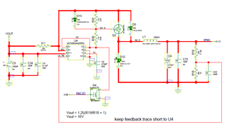
I think I may still be having issues with my supply! VOUT on the schematic is actually the +24V input. VFAN is +16V output to a fan. My Ct is currently 2200pF. My inductor current doesn't consistently go back to 0, as shown in the datasheet. Is that a problem? The output voltage seems to regulate. Even if I use a purely resistive load, the inductor current waveforms isn't cyclic and doesn't consistently go back to 0A. The P-Channel FET runs cool though and the output voltage seems to regulate fine.
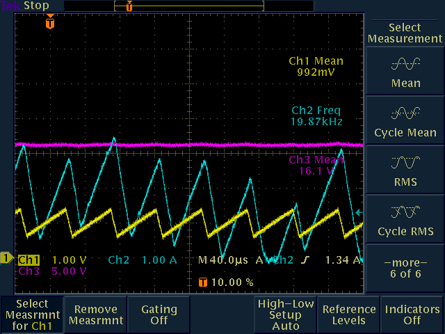
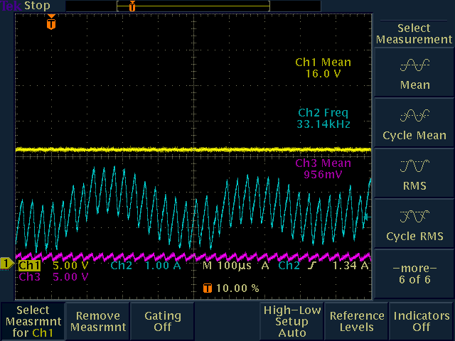
The Oscope plot is with my FAN attached:
Purple trace is the output voltage
Yellow is Ct pin
Blue is inductor current
The gate pin (not shown in plot) of the FET appears to turn on and off nicely. The duty-cycle various though even with a resistive load. I created a test board with a solid bottom ground plane and worked to control current flows and such per the layout examples. I tried placing a cap of varying sizes across the lower feedback resistor(R18). It changed things, but didn't make the waveform uniform. Q4 will be used to bypass the switcher for an output voltage of +24V, thus two-speed fan control. I don't have a lot of experience with switching power supplies, so any help is greatly appreciated.