This thread has been locked.

If you have a related question, please click the "Ask a related question" button in the top right corner. The newly created question will be automatically linked to this question.

BQ25731: BQ25731 query

Part Number: BQ25731

Hi

The application of BQ25731 is shown in the figure :

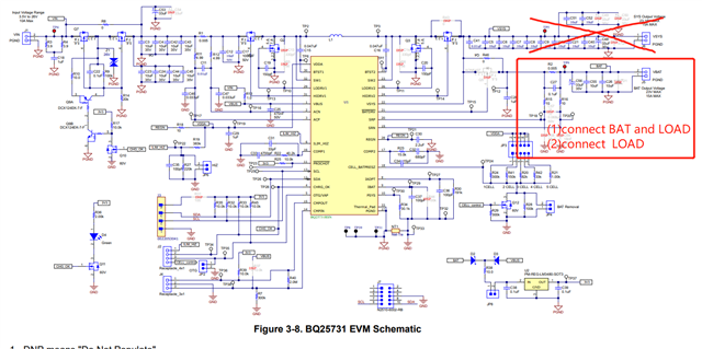
The following problems are encountered in the testing process:

Battery and load are added at the VBAT end (currently only in the VBAT end of the pull-load experiment).

The input voltage is 24V, the input current is limited to 1.6A, the charging current is set to 5A, the charging voltage is 13.2V, and the load meter is used to pull the VBAT.

When the VBAT is pulled to the input current of 0.45A each time, the VBAT voltage will drop to 0V。

How to solve this problem? Can registers be configured to solve this problem?

Thanks

Star

  • Hi Star,

    First of all I want to ask where they are pulling the load from. Are they pulling it from the VBAT pin directly (right side of schematic, number 2 blue circle below) or from the other side of the sense resistor (left side of schematic, number 1 circle below)?

    They should not be pulling from VBAT pin directly as the controller uses the sense resistor to detect current information. 


    Questions:
    1. How much load are they pulling from the battery?

    2. Where are they measuring when they said VBAT = 0? If they are measuring directly at the battery, then it sounds like a short circuit or the battery protector (external to the IC) opened.

    Can they try the same test without an adaptor present and pull load from the side of the resistor (left side of the schematic, number 1 blue circle below) not connected to battery? If it works, add the adaptor and try again.

    Thanks and I hope this helps,

    Peng

    *If my answer solves your question, please press "This Resolved My Issue" on the thread.  

  • Hi Star,

    As it has been one week and no replies from you, I assumed that the problem has been resolved and I will close the thread. If you have more questions, feel free to start a new thread and reach back to TI on the E2E forum.

    Thanks and I hope this helps,

    Peng

    *If my answer solves your question, please press "This Resolved My Issue" on the thread.  

  • Hi Peng

    Thanks for your reply.

    We expect that the number 2 can directly load about 1A. At the same time, we will add batteries in number 2 and charge them when necessary.(Both load and battery are connected to number 2, maybe the battery does not work, only pull load)

    Thanks

    Star

  • Hi Star,

    Once again, battery and load cannot be on the same node. They need to be on the opposite side of the sense resistor.

    The controller uses the sense resistor to detect current information, so both charge and discharge path need to go through the SRP/SRN sense resistor.

    Thanks and I hope this helps,

    Peng

    *If my answer solves your question, please press "This Resolved My Issue" on the thread.