


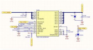
In my application , i use TPS259824ONRGET , input voltage 12V, max current 10A。
I have already done the PCB design ,the board is already produced , now it is being tested. during the debug process, I discover one problem which I cannot explain or solve.
the device can be switched on with no load , then I can raise load to over 12A , it runs normally.
However if the output port has a resistance of 4Ω (12V3A) or 6Ω (12V2A) , the device can NOT be turn on normally.
by watching waveforms , TPS259824 will try to restart for 4 times (which is one designed feature). At each time, the output voltage will only raise up to about 2V, afterwards it is shut down.
waveform of output voltage is as below:
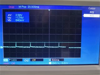
Anyway, if the load is smaller like 12Ω(12V1A),It can operate normally.
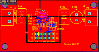
this is my Schematic and PCB diagram , I would like a kind engineer help me review them and find the design fault.
I have tried many methods to avoid the above problem but not worked , as below :
-
remove the output electrolytic capacitor.
-
remove the output Schottky diode
-
raise the ITIMER capacitor(C401) to 100nF for extending transient time.
-
raise the DVDT capacitor(C403) to 100nF for reducing the rising voltage slew rate.
-
smaller the ILIM resistor to 50Ω
the problem still occurs after trying these methods.
I have 2 questions:
-
Why does this happen?
-

