Hi,
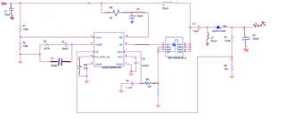
I am analyzing my regulator circuit with the following parameters (Input = 3V to 36V, Output = 3.3V, I_Out = 0.5A). The circuit works up until about a 3.95V input, from there the square wave out of the drive pin flips from 14% duty cycle to 86% duty cycle and I no longer get 3.3V at the output. This translates to the drain producing a more distorted wave form the closer it gets to 3.95V, until it goes below and appears very unstable and noisy.
What would be the main cause for the drive pin to be inverting? I incremented R_SL for external slope compensation and noticed no change. The design is more or less based off of Webench for those parameters.