This thread has been locked.

If you have a related question, please click the "Ask a related question" button in the top right corner. The newly created question will be automatically linked to this question.

TPS274160: Raise time and Falltime

Part Number: TPS274160

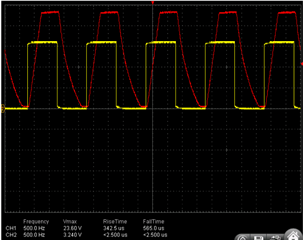
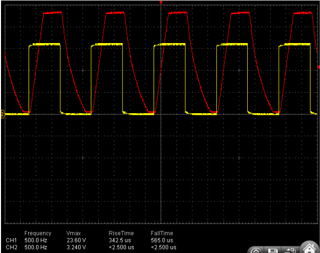
We are using TPS274160BRLHR in our industrial digital output design, We observed that output put raise and fall times are at maximum (around 330ms) when we check the output using DSO.

Is there any way to reduce the raise and fall time?

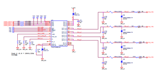
We have Zener, TVS and series resistors at the output, those are influencing fall time.

But raise time should be around 130ms while operating @25C.

We are trying to switch 24V output at 500Hz.

Please help me solving this issue

  • Hi Manjunatha,

    Thanks for contacting us. First of all, from the waveform it seems the rise time is 340us, while in your post you are stating it's 330ms. Just to make sure it should be microsecond correct?

    1. First of all, can you zoom in the waveform and use cursor for measurement? It gives a more accurate data.  

    2. Could you provide your circuit schematics?

    3. Could you provide a screenshot with Vout and EN show in the same screen? The timing there might give us more clue.

    4. Why rise time here is a concern in your application? Is it affecting the effective duty cycle?

    From the datasheet, the maximum rise time should be ~150-20us which is 130us. So theoretically it should be shorter.

    Regards,

    Yichi 

  • Hi Yichi,

    Yes, you are right. rise and fall times in microseconds and not in milliseconds.

    3.3V yellow signal is the EN and Red one is Output.

    With this raise time we are not able generate PWM over 500Hz frequency.

  • Hi Manjunatha,

    Could you share the value of RC filter at the output? I can't see the value clearly through the pic. Could you try to reduce the resistance at the RC filter to see if it helps? Additionally, what's the purpose of the RC filter at the output instead of just capacitance to smooth the voltage?

    Regards,

    Yichi

  • Hi Yichi,

    C = 22nF and R 220E, R is used to protect Zener. ( intrinsic safety barrier).

    I have un mounted the capacitor and Fuse and measured the IC output. With this fall time reduced to around 110uS, but rise time still remains same. i.e, > ~ 330uS.

    Regards,

    Manjunatha 

  • Hi Manjunatha,

    What's the load current while testing, and what's the current limit setting? Could you collect the current waveform as well? I'm thinking if somehow the current limit is triggered, the Vgs will be reduced and the time to turn on the FET will be slower as well.

    Regards,

    Yichi

  • Hi Yichi,

    Current is limited to 100mA.

    output is not loaded, directly probing the voltage using DSO without any load.

    I will be sharing current wave form with load asap.

    Regards,

    Manjunatha

  • Sure. Looking forward to the waveform. Also another thing to try is to raise the current limit (to a high value) to see if the situation improves.

    Regards,

    Yichi