This thread has been locked.

If you have a related question, please click the "Ask a related question" button in the top right corner. The newly created question will be automatically linked to this question.

BQ76200: Some question about BQ76200

Part Number: BQ76200

Dear Expert

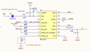
For BQ76200, there are several questions;

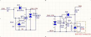
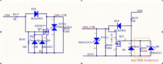
1.CHG\DSG drive level has been around 10.5V, less than the typical value of 12V;

2. When the resistance value of R167 is greater than a certain value, the CHG/DSG level wave forms a sawtooth shape;

  • Hi Gabriel,

    The application note https://www.ti.com/lit/pdf/slua794 may be helpful to understand the charge pump operation with the BQ76200.

    1. CHG and DSG voltage comes from the charge pump.  The FET drive voltage is measured with the specific load shown in the data sheet.  Parts will vary device to device and over the operating conditions.   As load is added the voltage will drop.  

    2. The sawtooth shape of the high level is common, the amplitude and frequency will change with the load. The 430k load of R167 seems like a lot.

  • Dear Expert

    Thanks for your reply.

    My customer still a lot confuse about second point 

    1、You said the 430k load of R167 seems like a lot. When I look at the resistance in SLVA729A, the resistance value is 1M ohms.

    2、Yous said the amplitude and frequency will change with the load ,could you tell me what's the relationship of he amplitude and frequency with the load  .

    Attached BQ76200 full schemetic :

  • Hi Gabriel,

    1. I did not mean to be confusing.  The smaller the resistor the more current or load.  SLUA729 uses 10 M gate-source resistors, R3 and R4 in the clip you shown. With a 12 V charge pump current will be 1.2 uA each or 2.4 uA total load on the charge pump.  The red square shown is the RGS of the precharge resistor, 10 Mohm

    With the circuit clip shown from the customer, at 12V:

    R161 10M, about 1.2 uA load

    R165 1M, about 12 uA load

    R166 10M, about 1.2 uA load

    R167, 0.43M, about 28 uA load.

    These are estimates because of series resistors and diodes, but total estimate is about 42.4 uA.  That is a lot of load for the charge pump.  R167 is the largest contributor to that load. 

    2. See the application note https://www.ti.com/lit/pdf/slua794 figure 3.  If there were no load the voltage would not drop much and it would be a long time before the charge pump ran again to raise the voltage.  The frequency would be low.  As the load increases the voltage will drop more quickly and the charge pump will run more frequently, so the frequency is higher.  The added load will slow the rise somewhat, but generally the frequency will increase with load.  When the charge pump is overloaded so that it pulls into UVLO, the voltage will generally drop quickly and the load is turned off by UVLO so it rises quickly, this will be the highest frequency operation.  There is no known equation to describe it.

     As described in section 2.1 of the application note, 40 uA may be the limit of the charge pump to stay out of UVLO.  You would like to have good margin for the design so some lower value of load current may be desired.

  • Dear Expert

    BQ76200 standby power consumption up to 3mA, too high.

    When the BQ76200 is on standby, it still needs to give the drive signal to the MOSFET, the Pack foot test has about 2.5mA current.The entire IC consumes up to 3mA.How to solve it?

  • Hi Gabriel,

    The BQ76200 is a charge pump, it has a current multiplier effect on the supply current. If the multiplier is 5x with a 20 uA load, input current would be about 100 uA.  

    PMON circuit takes a significant bias current, this will often be reduced by duty cycling for measurement.  The PCHG takes less significant bias current.  These currents are not in the data sheet, see an example in the application note https://www.ti.com/lit/pdf/slua794 figures 7, 8.  

    If current is from PCHG solutions would be to enable PCHG only when the charger is present or use a N-ch with Zener to control the precharge FET so that the designer can set their own bias current.

  • Dear Expert WM

    Thanks four your replying!

    I disableed PMON  Pin, and the Pack Pin current is down to 10 uA in stanby mode.

    Could u tell me is there any affect other functions or hidden trobule.

  • Hi Gabriel,

    The BQ76200 behaviors which may not be obvious from the data sheet are described in  https://www.ti.com/lit/pdf/slua794.  The other application notes in the folder cover other use cases which may be of interest, but there should be no hidden trouble.