This thread has been locked.

If you have a related question, please click the "Ask a related question" button in the top right corner. The newly created question will be automatically linked to this question.

BQ25703A: BQ25703A technical support

Part Number: BQ25703A

Hi,Ti

We are charging three 18650 battery packs in series, and the charger is the 12V adapter. The attachment is our schematic diagram, please help to check whether the configuration parameters are OK.
In addition, please help to provide the I2C control case of charging for our reference.2860.BQ25703A.pdf

  • Hi Dominic,

    Thanks for reaching out.

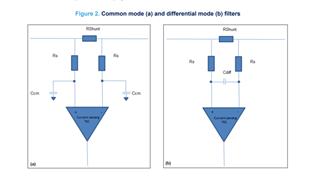
    1. For ACP-ACN current sense filter, please refer to the EVM for values to use. Also recommend a differential mode filter on the pins.


    3. If you actual install the SW RC snubber, good to calculate the resistor loss.

    /cfs-file/__key/communityserver-discussions-components-files/196/7103.RC-Snubber.pdf


    4. Have the low side gate capacitors as "Do not populate"

    5. Make sure you have pull-ups on SCL, SDA, and /PROCHOT.

    6. Please refer to EVM on the COMP1 and COMP2 compensation values.

    7. Add a cap (or a placeholder) between SRP and SRN for differential mode filter.

    8. Resistor from IADPT to ground should be 137k corresponding to the 2.2 uH inductor that you are using. This value is critical.

    9. You can place a filtering cap across the PSYS resistor if needed.


    I am not too familiar with the rest of your circuit (connector as well as the switch network) and I will not comment of them.

    For I2C control, please refer to the register maps on the datasheet.

    https://www.ti.com/lit/ds/symlink/bq25703a.pdf?ts=1624027299590&ref_url=https%253A%252F%252Fwww.google.com%252F 

    Thanks and I hope this helps,

    Peng

    *If my answer solves your question, please press "This Resolved My Issue" on the thread.