A related question is a question created from another question. When the related question is created, it will be automatically linked to the original question.
If you have a related question, please click the "Ask a related question" button in the top right corner. The newly created question will be automatically linked to this question.
TPS568215 and TPS56C215 Does Mode Pin Resistor necessarily need a resistance with a tolerance of 1%? RM_L (kΩ) is 1%, RM_H (kΩ) is 5%, is there a risk?
Suppose we choose RM_L 20K and RM_H 120k Light Load Operation=FCCM, Current Limit=ILIM, Frequency (kHz)=800HZ What is the range of RM_H? RM_H min=?? typ=120k max=?
Actually, we recommend 1% of resistor for both RM_H and RM_L so that the mode variation can be within +/-10% in all conditions.
Since the internal LDO is 4.7V, for your application, the typical value of Vmode is equal to 0.671V. The upper and lower Vmode should within 0.6039-0.7381. We can get the RM_H value is about 107K to 135K if RM_L is fixed to 20K. Taking some margin into consideration, 110K to 130K maybe safe with fixed 20K. If the 20K also use 5%, we need to leave more margin.
Why is it in TPS568215 datasheet 7.3.4 MODE Selection It is recommended to choose 5% resistance, as follows A guideline for the top resistor (RM_H) and the bottom resistor (RM_L) as 5% resistors is shown in Table 3
As long as one of (RM_H) or (RM_L)choose 1%, do you think there is no problem?
That has no effects on choosing Mode resistors. Internally this VREG5 is referenced to detect the MODE option. If external bias is added, it override the internal LDO and become VREG5 then.
You mean connect MODE to external 5V and this external 5V doesn't connect to VREG5? We don't recommend this. Mode detection is controlled by internal VREG5. We strongly recommend to connect MODE to VREG5, not external connection.
1.Why is it in TPS568215 datasheet 7.3.4 MODE Selection It is recommended to choose 5% resistance, as follows A guideline for the top resistor (RM_H) and the bottom resistor (RM_L) as 5% resistors is shown in Table 3
As long as one of (RM_H) or (RM_L)choose 1%, do you think there is no problem?
1. For mode pin config, it's preferred to use high precision resistor. The words that you mentioned "A guideline for the top resistor (RM_H) and the bottom resistor (RM_L) as 5% resistors is shown in Table 3" can be understood as "the 5% resistors can be endured by following the recommended resistance value in Table 3".
2. Appreciate your effort for the analysis. There's a small error that %5 resistor cannot bring +/-10% variation for the mode pin voltage. Mode pin voltage is divided from VREG5, the ratio equals to RL/(RL+RH), that's 1/(1+RH/RL). So we could know larger RH/RL can cause smaller ratio.
So the largest RH/RL in range is 180k*1.05/(51k*0.95)=3.9. With 4.7V VREG5, smallest mode pin voltage for this config is 0.959V. The smallest RH/RL in range is 180k*0.95/(51k*1.05)=3.193, largest mode pin voltage for this config is 1.12V. So the range should be 0.959~1.12V.
But I think maybe it's better not to think too much about the calculation here, since there could be other internal circuit affecting the mode pin voltage detection. I advise to just follow our datasheet recommendation to use the device.
4. Do you want to use other resistance value other the the recommended one? I recommend to follow the table in our datasheet. We can guarantee the performance just for the application following our datasheet's specs and guidelines.
For TPS56C215, firstly we strongly recommend to use 1% resistor for Mode pin resistor. Your calculation is correct, if using 5%, some of the mode voltage will have overlap. That's why we strongly recommend 1% resistor. For DS description, we need to correct it and 5% is not correct. Sorry for the misunderstanding.
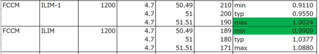
As for your last question, there is the possibility to have overlap as below. Recommend to use 1% mode resistor.
I know that RM_L=51k(1%), RM_L=180k(5%), RM_L=51k(1%), RM_L=200k(5%) overlap, But what I want to know is, mode resistance range(IC decide range ) E.g 5 mode 0.9V~0.99V 6 mode 0.99V~1.09V
I recommend the data sheet RM_L = 51K RM_H=180K mode 6 Need to be modified, ratio=0.220779221 is too low, I feel very confused RM_L = 51K, RM_H=180K typ=(22%)*VCC. Not in (22.5%-24.5%)*VCC, range
Really sorry for misunderstanding. I should correct my last response.
For 5 Mode, [(6/32)%-(7/32)%]*VCC, it is (18.75%-21.875%)*VCC.
For 6 mode, [(7/32)%-(8/32)%]*VCC, it is (21.875%-25%)*VCC.
There is a same range in the middle, so we need to leave some margin for 21.875%. For example, (18.75%-21.5%)*VCC for mode 5 and (21.9%-25%)*VCC for mode 6.
Yes, you are correct. For 6 mode, the setting in the recommendation table is more close to margin. Setting to ~23%*VCC should be a good point. 160K or 168K usual value resistor for RM_H should be good choices.
Although for 6 mode, the setting is close to margin, but we didn't receive any customer feedback about this mode detection error.
At last, Aaron, really thanks for your questions. I will discuss with team and try to make it more clear in DS.