This thread has been locked.

If you have a related question, please click the "Ask a related question" button in the top right corner. The newly created question will be automatically linked to this question.

Failing TPS54331 Supplies

Other Parts Discussed in Thread: TPS54331, TPS54232, TINA-TI

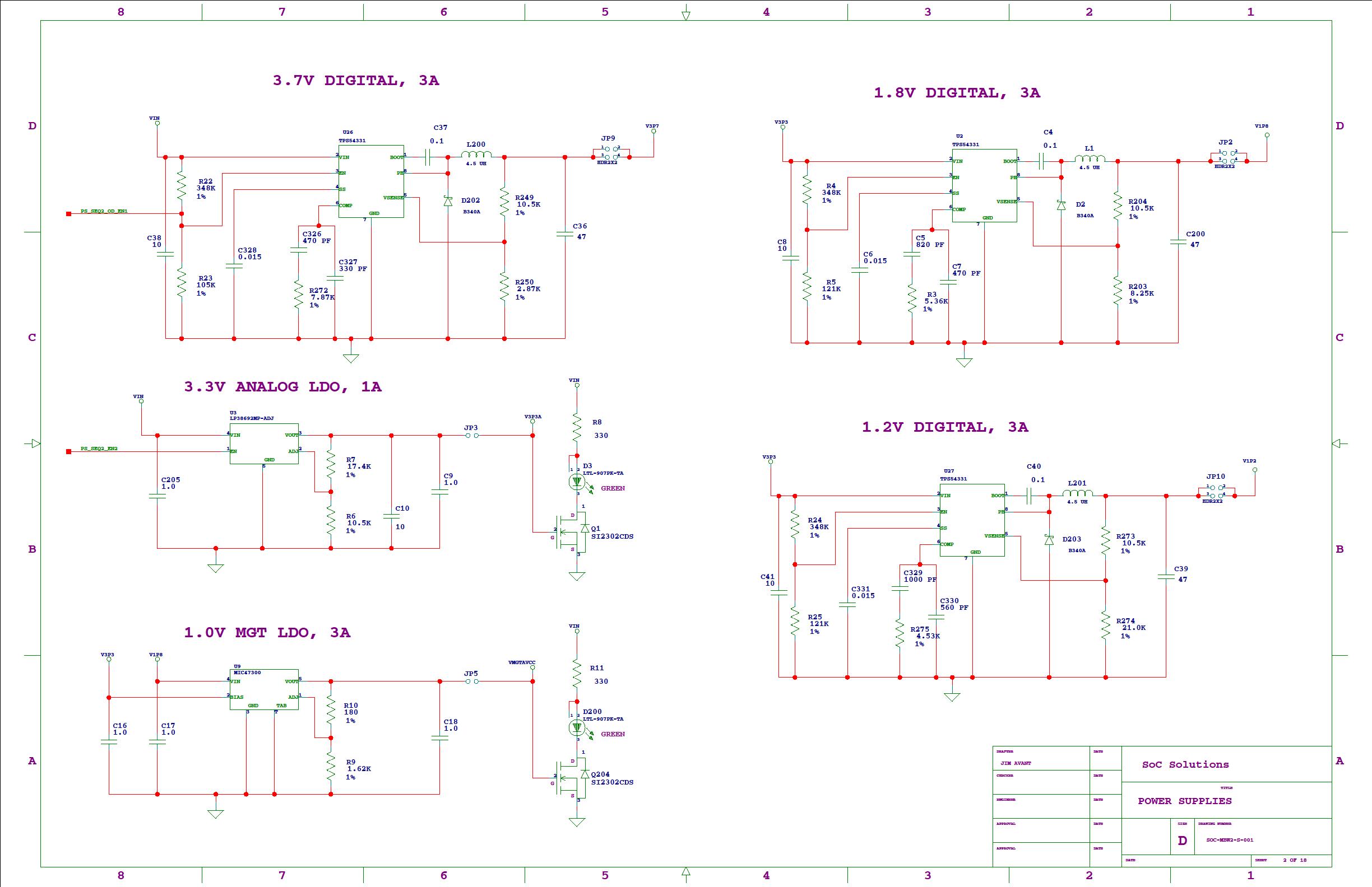
I have designed a board with three TPS54331 parts.  In the past I have successfully designed boards with similar TPS54232 supplies and have done several other boards with other switching supplies. One of the 3 supply circuits is working (3.7V output) but one two are not (1.8V & 1.2V).  I made the mistake of driving these 2 supplies with 3.3V instead of the 3.5V minimum in the datasheet.  I increased the 3.3V supply to 3.55V but these 2 still are not working while the one driven at 5V is working fine.  I also tried replacing both TPS54331 parts and a few of the components around them but the circuits act the same.  The output voltages don’t come up to the proper voltage (0.85V & 1.01V instead of 1.8V & 1.2V respectively).  I even bought new parts from a different vendor and replaced again with no help.  I'm using 4.5uH, 4A rated inductors for all 3 supplies.

I went back to the SwitcherPro software and re-entered the circuit for the 1.8V supply and saw that it was not very stable.  I fixed some components and let it pick others until I had a very stable design.  Then I swapped out components on the board to match and I see no change at all in the behavior.  Instead of the desired 1.8V output I still see about 0.85V.  I did the same redesign with the 1.2V circuit with no improvement.  I tried arbitrarily changing output resistor values and got an increase in output voltage, but not near 1.8V.

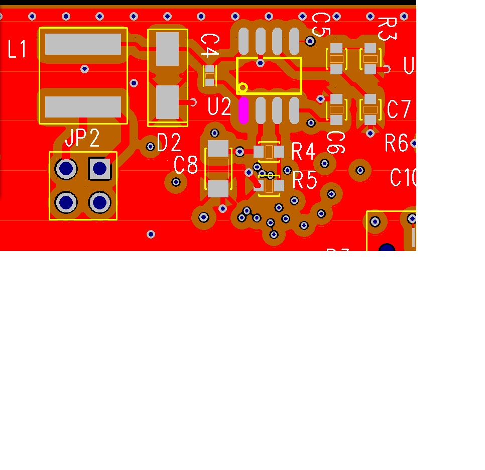
I am testing with the non-working supplies unloaded.  I don’t see any evidence of switching on any of the pins.  I have reviewed the layout and don’t see any issues there.  This is a 16-layer board with LOTS of ground.  The working circuit is placed side-by-side with one of the non-working circuits and the layout is almost identical for both circuits.  Is there a reason this part would not work with light or no load?

I built up a bare board with JUST the 1.2V & 1.8V supplies.  I have varied the input voltage from 3.5 to 6V and cannot find any voltage at which both supplies work.  I have been through the datasheet calculations and don't see any problems with my designs.  I have to respin this board soon and need to make a decision to ditch this part and start over if I can't find a fix so prompt help would be sincerely appreciated.

Thanks,

Jim

  • Can i see schematics and waveforms?  If you are building up these designs on bare boards with only the supply circuits populated, then I have to beleive it is a layout issue.  Did you follow the layout guidlines?  The most critical issue is to have the input bypass capacitor as close to the IC as possible.

  • OK, how do I do that?

    Jim

  • You should be able to attach files. Use the "paper clip" icon second from right  above

  • Please see attachments. Input cap is C8.

  • Try removing, R4, R5, R24 and R25.  let me know if that works.  Otherwise I will need to see waveforms.

  • That has already been tried.  Nothing I can do with Ven makes any difference.  What I find most odd is that as I crank up the input voltage, one supply seems to regulate for awhile, then as the voltage increases, it goes out of regulation, while the other one starts regulating.  I can't find an input voltage that makes both circuits stable, while the design software indicates they should both be very stable across a wide range of input voltages.

    Jim

    TPS54331.zip
  • What are the *.TSC files?  I can't seem to open them.  Also can you provide any waveforms?  I would like to see PH and Vout for sure and any other waveforms that demonstrate your problem.  Are you measuring the low output voltages with a meter or are you observing the values with a scope?  It may be that you are in low headroom drop out AND eco-mode at the same time.  In this case you may be getting a dc output with around 2.1 V of ripple that will make the output appear to be low when measured with a volt meter.  The circuit will exhibit breif periods of switching followed by extended sleep time.  From your decription, this sounds like it could be the issue, but I will have to see waveforms to be sure.

  • Moderation reply.

  • The files are Tina-TI files.  After loading up the reference design, modifying parameters and running a simulation, Im not sure Im any closer to an answer.  Please see the two attached files.  Both of these circuits worked fine with no warnings in SwitcherPro Desktop, but they don't work in simulation.  I played with one of the circuits and got it to work somewhat at full load, but it fell apart at light load. Can you please help me to determine why these circuits don't work?

    Thanks,

    Jim

  • I can tell you that switcherpro does not take into account any of the esoteric operating modes of the TPS454331.  That includes low headroom drop out and eco-mode.  What I think you are seeing is eco-mode and low headroom drop out occurirng at the same time.  I f ai can see some wave forms < I may be able to make a call on that,


  • John,

    The scope waveforms show no hints.  They are very flat with very little noise.  Certainly no evidence of instability or stepping.

    Probing the outputs, the 1.8V supply seems to regulate at input voltages just above 4V, but the 1.2V supply shows no signs of regulating at all.  The output voltage varies as the input voltage varies.  In other words it just looks like a resistor.  But still the output looks very flat.

    Thanks,
    Jim

  • so, no switching at all on the PH node?  I will try to look at your sims tomorrow.

  • John,


    Any luck? I'm building a 2nd proto board now and I really need at least the 1.8V supply working.  I'm rewiring the input so it will run from 5V this time.


    Thanks,

    Jim

  • I was expecting you to provide waveforms.  Do you have any that show your start up issue?  I ran teh tina files and they do not work w/ 5 V input, but seem to work fine with Vin = 12 V.  I will have to see if I can find out who did the model and look inside.  Getting teh model to work is one thing, but I am ore concerned w/ your circuit.

  • Unfortunately I do not have any waveforms worth sharing.  As mentioned before outputs are pretty quiet and at DC, just the wrong voltage.


    Also unfortunately I don't have a voltage higher than 5V in my system.  I guess what I'm most interested in is how a supply rated for 3.5V input won't even work at 5V input levels.  I think you are right  to want to look inside the model.  But since the model seems to somewhat validate what I'm seeing in real life, I'd like to know what if any "undocumented" constraints there are on getting this silicon to work as a voltage regulator.  Was it mischaracterized?


    Sorry if I seem short but that's the way time is running on this issue.


    Thanks,

    Jim

  • i think that is a model issue not a device issue.  I have passed that on to the modeling team and they are baffled for now.  They are going to run it in teh unlocked master where they can access the internal nodes.  So far as I know teh actual silicon should work w/ 5 V input, especially if you do not have any resistors connected to EN to set external UVLO.  The tolerances on teh external UVLO can possibly cause teh EN threshold to be too high at low voltages.  If I have a board handy I wil try it in teh lab.

  • I checked a baord.  the start threshold for VIN with no UVLO resistors on EN is 2.95 V.  Exactly what I would expect.

  • John,


    OK, thanks.  I should have my 2nd board modified and ready to check out tomorrow afternoon.  I'll let you know what I find.

    Thanks,

    Jim

  • John,


    I have both supplies working now.  Apparently the EN input doesn't work quite as documented.  With no resistors the design works.  I haven't checked across a range of loads yet but so far so good.


    Thanks for all your help!

    Jim

  • If memory serves, That was one of the first things i suggested.  EN works as documented, nut the tolerances are such that it is best suited for "coarse settings"  such as if you have a 12 V input ant want the supply to turn on about 9V  and off about 8 V.  Trying to get very fine control can lead to problems.  I'm glad you got it working.