This thread has been locked.

If you have a related question, please click the "Ask a related question" button in the top right corner. The newly created question will be automatically linked to this question.

BQ25883: Reviewing BQ25883's layout

Part Number: BQ25883

Sir,

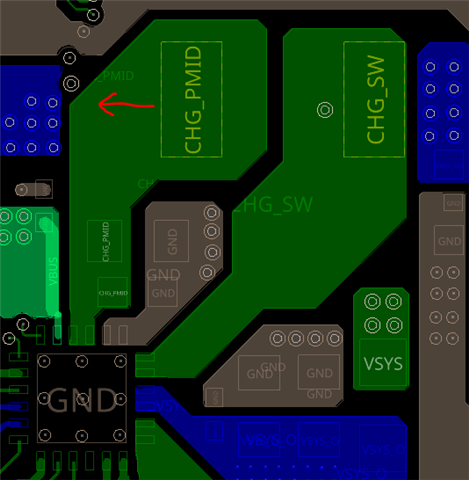
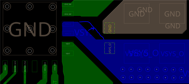
   This is Mickey Lee, EE lead of Electro-Acoustic R&D, Luxshare-ICT (Taipei), our new project adopts the boost-mode battery charger IC BQ25883 and

   related schematic & layout are also attached in here, please help to review and provide your adjustment recommendation

M10-0618-1500.zip.M10_Charger_IC_0618.pdf


  • Hi Mickey,

    Here are my comments on the BQ25883 schematic.

    1. The absolute maximum sink current for the STAT pin is 6 mA, as shown in Section 7.1 in the datasheet. I don't know the forward voltage drop for your white LED (LED1001), but I suspect that the current limiting resistor must be larger so that the STAT pin current is <6 mA. I suggest increasing R1011 from 220 Ω to a value between 1 kΩ - 10  kΩ.
    2. R1013 is not required. We include this resistor on the BQ25883 EVM because measuring the voltage drop across the sense resistor gives us a convenient way to calculate the system current, but you can leave this resistor out of your schematic.

     For future reference, we have a schematic checklist document for the BQ2588x charger family here:

     5584.BQ2588x Schematic Checklist.pdf

    Here are my comments on the PCB layout:

    1. Please move inductor L801 to the left, slightly closer to the BQ25883.
    2. It looks like there is space to widen the VSYS copper pour.

    Best regards,

    Angelo

  • Thank you very much and we'll follow these comments accordingly.