This thread has been locked.

If you have a related question, please click the "Ask a related question" button in the top right corner. The newly created question will be automatically linked to this question.

LM5105: LM5105 shoot though issue

Part Number: LM5105
Other Parts Discussed in Thread: TINA-TI

I have an issue with the LM5105. 

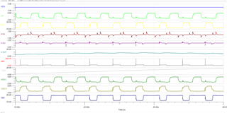
It is shooting through when the HO output is switching on, the LO turns on slightly.

I have simulated in TINA-TI and have posted an video explaining the problem.
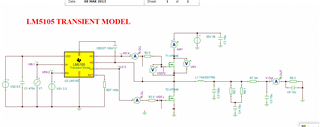
Old TEC & old switcher.TSC

  • Hello Ahmad,

    thank you for the video on the simulation concerns that you are seeing. There are a several things going on which I can explain and give some advice.

    I see that you are running what looks like a fixed duty cycle from startup to steady state. When I test an open loop power board in the lab with this same setup, regarding fixed duty cycle I see the same behavior regarding the very large currents until the output voltage rises. What is happening is you are charging a capacitor which is at 0V initially and you are imposing a voltage across the output inductor during the "forward" or conducting pulse and during the HO off pulse is when the volt-sec of the inductor and the current ramp will normally decline. Since there is 0V on the output you are ramping up the inductor current but during the high side off time there is very little voltage for the inductor current to decline. So it is ramping up cycle after cycle to very high levels.

    In a complete system with a controller, there is soft start to take care of this during startup, where you start with very narrow PWM pulses to prevent the very high inductor current during startup.

    The voltage that you see rising on the LO and HO outputs during the switching of the switch node edges, is from the drain to gate miller charge of the MOSFET which couples charge into the Vgs during the Vds rise and fall time. One way to reduce this is to use lower Qg MOSFETs especially the drain to gate charge. Another way to reduce the Vgs perturbations is to add some gate to source capacitance on the MOSFET which reduces the miller charge affect on Vgs. 

    The shoot thru current that you are showing will actually occur in a sync buck power stage when the inductor current is always above 0. When the low side device turns off, there is still current flowing in the inductor which forces the current to flow thru the MOSFET body diode. The switch node is low and being clamped by the body diode of the low side FET. When the high side FET turns on, there is a reverse recovery time of the low side body diode, so until the body diode turns off of the low side FET, there can be a high current thru both MOSFETs. This is an effect of the MOSFET body diode recovery time, and the driver timing cannot resolve this issue. Mosfets with faster body diode recovery and slowing down the turn on of the high side MOSFET are the best solutions for this current spike.

    Regards,