Hello TI experts,
I am trying to design an adjustable constant current supply using the LM5117 chip that can source ~0-2A. Currently, I plan to modify the CC example in the datasheet:
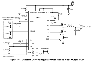
Originally, I tried to replace the voltage divider in the current control box (bottom left) with a potentiometer. The potentiometer seems to have little to no effect, however.
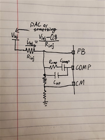
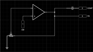
After looking at the datasheet again, however, I realized that because V_CM ~= 2*I_out*R_s*A_s, and the reference voltage for the error amplifier is 0.8V, the small 40milli-ohm current sense resistor is probably too small when trying to regulate the output to 100mA (V_CM = 2*0.1A*40E-3 ohms*10 = 0.08V << 0.8V), for example. My next idea would be to add a variable gain op amp to amplify the output of the CM pin, something along the following lines:
Firstly, does this approach make sense, or do I have a conceptual misunderstanding of how the chip works? Secondly, the capacitor connecting the COMP node to the FB node, although it is in the datasheet example, I'm not quite sure how to pick its value, as the datasheet equations consider a filter network with the resistor in series with the cap there.