This thread has been locked.

If you have a related question, please click the "Ask a related question" button in the top right corner. The newly created question will be automatically linked to this question.

TPS7H2201-SP: TPS7H2201-SP

Part Number: TPS7H2201-SP

Hello,

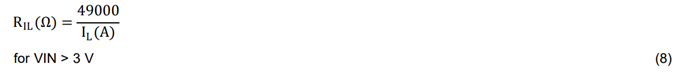
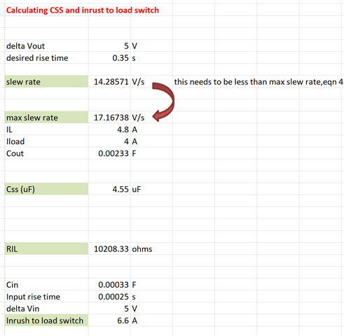
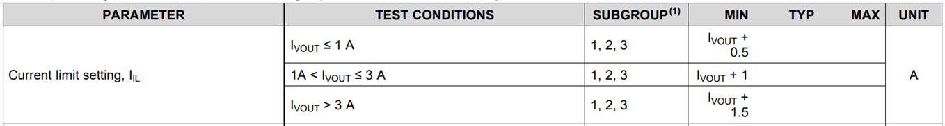
I would like some guidance as to what value of pull-down resistors to use for the CS and IL pins please.

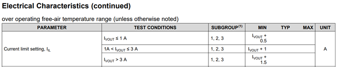
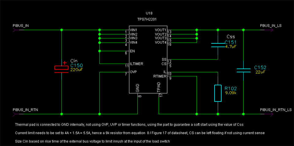
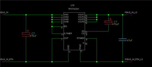
I am not using the OVP, UVP, or the timer functions and have permanently enabled the device as shown below.

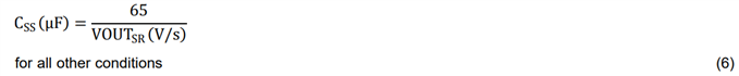
By setting Css to 470 uF and with Vin=+5V, I have set the rise time to approx. 138 mS.

Please advise ...

Kind regards,

Rajan

  • Hi Rajan,

    Both resistors will depend on what load current your design uses.

    The IL resistor should be chosen so that the programmable current limit is at least 20% higher than the current limit value that you select (due to the +/-20% accuracy of the current limit). You will also need to make sure the current limit is not set above 7.5A due to the device's maximum current rating of 6A. The minimum current limit you could use will depend on your load current - I've attached an image of the datasheet spec below and linked to the page in the datasheet that shows the specification here.

    For CS, the range of resistor values you can use will depend on your load current. The current output from the CS pin is equal to the load current of the switch divided by 41.500. The voltage on this pin must not exceed VIN-0.4V (which is 4.6V for your design), so you should choose the CS resistor that will ensure this requirement is met based on the highest CS current you expect. This pin can also be left floating if you are not using the current sense feature. 

    Thanks,

    Sarah 

  • Sarah,

    Thank you for your reply.

    I will not need current sense so will leave pin CS floating.

    I don't want the current exceeding 4A so will size RIL for 4A + 20%, figure 17 in the datasheet suggests around 13k.

    Are you happy with my schematic below? Are you happy with my value of Css to achieve a rise time of just over 100 ms?

    Kind Regards,

    Rajan.

  • Sarah,

    Is the current limit based on steady-state current through the load switch and/or inrush current at power-on? The input capacitance connected to the load switch will impact the latter?

    Kind Regards,

    Rajan

  • Hi Rajan,


    I don’t notice an issues with your schematic once you add the resistor for the IL pin.


    I would recommend using equation 8 in section 8.3.3 of the datasheet to obtain a more precise value for the IL pin resistor. Using a 13 kOhm resistor would result in a nominal current limit of 3.75A, but due to the 20% accuracy of the current limit there may be some occasions where the current could reach ~4.5A (3.75 + 20%) before the current limit triggers. This may or may not be an issue for you, but if your design cannot exceed 4A, you will want to set the current limit 20% below this value to guarantee the current limit always goes into effect by the time the current reaches 4A.


    Equations 3 and 6 from section 8.3.2 of the datasheet show that Css = 1.3 uF in order to obtain a 100ms soft start time for your system. As you mention, it’s possible for the current limit to experience a false trip when the device is enabled. Equation 4 shows the relationship between the current limit, load current, output capacitance that determines the maximum VOUT slew rate that can be set by Css to safely avoid such false trips.  

    Thanks,

    Sarah

  • Sarah,

    Thank you for the update, I have re-calculated Css and RIL using the equations in the datasheet and my calculations are shown below. One further question, when calculating max. slew rate, i.e. equation 4, what vlaue should I use for Cout. In my case, the total input capacitance after the load switch is 2mF ans should I add this to the specific Cout connected to the load switch to calculate the max. slew rate and ensure the nominal slew rate is less than the max. value.

  • Hi Rajan,

    Yes, any capacitance that is seen at the output node of the load switch should be considered when calculating max slew rate since it will all contribute to the current demanded through the load switch.

    There is one more thing I notice about your current limit setting. The datasheet also specifies a minimum current limit setting that is dependent on the load current. For loads larger than 3A, the current limit needs to be set at least 1.5A above the load. If the nominal continuous load for your design is 4A, this means the minimum current limit setting will be 5.5A.

    Thanks,

    Sarah

  • Sarah,

    Given that I have nearly 2mF of capacitance already connected to the output of the load switch, is the 10uf (min) at the output of the load switch, recommended in the datasheet, really necessary?

    Thank you for spotting the 5.5A current limit.

    kind Regards,

    Rajan

  • Hi Rajan,

    Yes, I would still recommend placing at least 10uF as close as possible to the output pins. This recommendation is less about adding an extra 10-uF to your total COUT, and more about the placement of the capacitor. Placing it as close as possible to the output pins helps minimize any effects that parasitic trace inductances may have on the operation of the device. 

    Thanks,

    Sarah

  • Here's my final schematic:

  • Hi Rajan,

    Thanks for posting your updated schematic. I would recommend updating RIL to 8.87k just to be on the safe side and make sure the current limit is not lower than the 5.5A required by the datasheet. You could also decrease the 0.35 sec soft start time a bit if you wanted to, but that is up to you.

    Thanks,

    Sarah

  • Sarah,

    In equation 4, should I use 4.8A (4A+20%) or 5.5A?

    Kind Regards,

    Rajan

  • Hi Rajan,

    You will need to set the current limit to 5.5A to avoid violating the minimum current limit spec, so you should use that value. 

    Thanks,

    Sarah

  • Thank you Sarah, I have now changed Css to 1 uF and the rise time at the output of the load switch has reduced to 70 ms. This means inrush will not damage the load. Thank you for all your help ...