This thread has been locked.

If you have a related question, please click the "Ask a related question" button in the top right corner. The newly created question will be automatically linked to this question.

TPS62740: Getting Sawtooth Waveform at the Output end

Part Number: TPS62740

Dear TI,

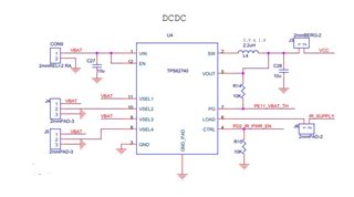
We are using the DC-DC TPS62740 IC in our the Device. we designed as per your reference document. 

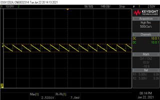
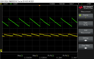
but when we check the output waveform in DSO we are getting sawtooth at the output of the IC.

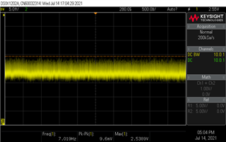
if we check on stable power supply we don't find any kind of waves at the output. 


  • Hi Vinayak,

    This is the expected behavior of the device at low loads when it operates in PFM (pulse-frequency operation).
    Take a look at Figures 31-33 from the datasheet.

    Regards,
    Davor

  • Hi Davor,

    Thanks for reply. can we smooth out the inverse sawtooth further, since it is interfering with analog circuitry. 

    Thanks in advance

  • Hi Vinayak,

    This device was made with efficiency in mind - so at lower output currents the mode of operation will be PFM. There is no option to force the TPS62740 to run in PWM mode since that would be very inefficient at low currents.
    The only other option that remains is to either use a converter with forced-PWM or possibly to try and add a ferrite bead/second stage filter at the output: https://e2e.ti.com/blogs_/b/powerhouse/posts/design-a-second-stage-filter-for-sensitive-applications 

    Regards,
    Davor 

  • Our device consumes less than 50mA current. 

    I tried to reduce the saw tooth by using 3rd stage filter and we have reduced it to up 2.8mV.

    can we reduce it further and make it almost straight ?

    green is normal output 

    Yellow is after using passive LC filter(2.2uH,10uF) 3 stage filter.

    is there anything that we can use and make it almost straight ?

    Thanks in advance.

  • Hi Vinayak,

    Since this is a switching converter (DC-DC Buck) theoretically you would need an infinite output capacitance to get a completely straight output voltage (with absolutely no ripple).So in the real world this is impossible.

    What are your requirements for the output ripple? For most cases 2.8mV is sufficient.

    Regards,
    Davor

  • Dear Davor,

    I am getting 2.8mV at Vout without connecting any Load to it. if I connect then it wont display any sawtooth wave but the noise is there upto 15mV. 

  • Hi Vinayak,

    Could you send waveforms of the SW node, VOUT and the current load for the case where the noise is up to 15mV?
    Perhaps the full schematic could be useful as well, if you could share it?

    Regards,
    Davor

  • my mistake, it is varying from 10mV to 11mV  when I connect to the my Load (MCU and discrete components)

    We have implemented our design as per TI's schematics.

  • Hi,

    First I should mention that a output voltage ripple of 9mV p2p is not a surprising result for the TPS62740. Most buck converters achieve that amount of ripple - check out the Figures 31. - 34. in the datasheet.

    Regarding the measurement I have the following thoughts/questions:

    1. The measurement could be corrupted by noise. What is the bandwidth of the measurement?

    2. The trigger is placed above the actual signal by 15mV - could you improve the triggering so that a clearer waveform can be seen (like in the first picture of this thread).

    3. Is the probe placed before or after the 2nd filter. If it is after the 2nd filter is the physical position of the probe on the same position as the measurement in the original?

    4. Please add the SW node waveform on the same scope plot and what is the total load at the output? Also when measuring the SW you can more easily trigger on it for a more clear measurement.

    5. Please use a lower horizontal scaling, 500ms/div is too much and we cannot see the waveforms well. Use something in the order of 1ms to 1us per div. Somewhat like in the Figures 31-34 in the datasheet mentioned before.

    Regards,
    Davor