This thread has been locked.

If you have a related question, please click the "Ask a related question" button in the top right corner. The newly created question will be automatically linked to this question.

BQ76952EVM: bq76952 spi

Part Number: BQ76952EVM
Other Parts Discussed in Thread: BQ76952, BQSTUDIO

Hi all,

I am trying to communicate with the BQ76952 from the EVM board over SPI but have not been successful yet.

With the bq studio I activated all the necessary registers like it is descripted: REG12 = 0x0d, REG0 = 1, Comm Type = 0x0f, SPI Config = 0x60 (changing entries without writing to the device and then loading the configuration of the device again, confirms that the BQ has the correct configuration ...)

Then I disconnect the jumpers on J19 and J16 to disconnect from the onboard MCU.

And on J15 I put a jumper to activate the pull-up to the 3.3V on the MISO line.

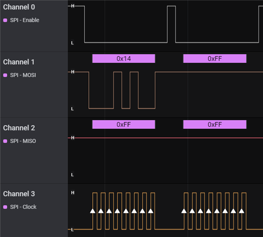
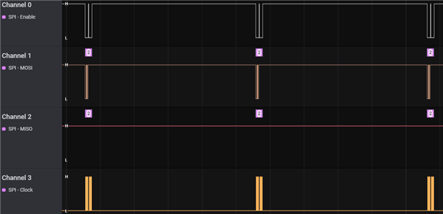
My programm from an external MCU writes two bytes on the MOSI line 0xE6 and 0x82, which I also crosscheck with an oscillsocope. (correct CS-line goes activ-low, correct CLK with 1MHz, and correct data)

But unfortunetly the BQ does not do anything. The MISO line stays high and it does not even return 0xff.

Do you have any idea what could be the issue? Did I forgot someting to configure or to activate?

Thanks for your support!

Best regards,

Martin

  • Hi Martin,

    I suggest first using the EVM to communicate in SPI mode to make sure that SPI communication is successful. With SPI Config = 0x60, you should not need a pullup resistor on the MISO line. It will drive 0V and 3.3V according to your REG12 settings.

    The steps to set up SPI on the EVM:

    • Set the registers in Data Memory (REG12 = 0x0d, REG0 = 1, Comm Type = 0x0f, SPI Config = 0x60). Measure the REG1 pin on your board to verify it is set.
    • Send the SWAP_COMM_MODE() command. This can be sent by click the SWAP_COMM_MODE button on the command window.
    • Now the device should be in SPI mode and should not communicate with BQStudio. Click the 'Refresh' button on the Registers screen to verify.
    • Set the J13 and J16 jumpers to the SPI position. Populate the J10 and J19 jumpers (make sure J19 is set to SPI position).
    • Restart BQStudio. It should now be communicating with the device in SPI mode.

    Once the EVM is working in SPI mode, you can write the settings to OTP if you want. This will change the default mode for the device. The instructions for writing to the OTP are listed in the EVM User Guide. This would also be a good time to connect a logic analyzer to see how the SPI format looks between then on-board MCU and the device.

    Now you can remove the J13,J16,J10, and J19 jumpers and connect your MCU. I suggest taking a close look at the examples in the BQ76952 Software Development Guide. I am also attaching a working SPI example below for your reference using an ARM based MCU.

    /* USER CODE BEGIN Header */
    /**
      ******************************************************************************
      * @file           : main.c
      * @brief          : Main program body
      ******************************************************************************
      * @attention
      *
      * <h2><center>&copy; Copyright (c) 2020 STMicroelectronics.
      * All rights reserved.</center></h2>
      *
      * This software component is licensed by ST under BSD 3-Clause license,
      * the "License"; You may not use this file except in compliance with the
      * License. You may obtain a copy of the License at:
      *                        opensource.org/licenses/BSD-3-Clause
      *
      ******************************************************************************
      */
    /* USER CODE END Header */
    /* Includes ------------------------------------------------------------------*/
    #include "main.h"
    
    /* Private includes ----------------------------------------------------------*/
    /* USER CODE BEGIN Includes */
    #include <stdio.h>
    /* USER CODE END Includes */
    
    /* Private typedef -----------------------------------------------------------*/
    /* USER CODE BEGIN PTD */
    
    /* USER CODE END PTD */
    
    /* Private define ------------------------------------------------------------*/
    /* USER CODE BEGIN PD */
    #define MAX_BUFFER_SIZE     10
    /* USER CODE END PD */
    
    /* Private macro -------------------------------------------------------------*/
    /* USER CODE BEGIN PM */
    
    /* USER CODE END PM */
    
    /* Private variables ---------------------------------------------------------*/
    SPI_HandleTypeDef hspi1;
    
    TIM_HandleTypeDef htim1;
    
    UART_HandleTypeDef huart2;
    
    /* USER CODE BEGIN PV */
    uint8_t spiData [2];
    uint8_t spiRxData [2];
    uint8_t rxdata [2];
    uint8_t busyData [2] = {0xFF, 0xFF};
    
    uint8_t TX_2Byte [2] = {0x00, 0x00};
    uint8_t TX_3Byte [3] = {0x00, 0x00, 0x00};
    uint8_t TX_4Byte [4] = {0x00, 0x00, 0x00, 0x00};
    uint8_t TX_Buffer [MAX_BUFFER_SIZE] = {0x00,0x00,0x00,0x00,0x00,0x00,0x00,0x00,0x00,0x00};
    
    uint8_t RX_2Byte [2] = {0x00, 0x00};
    uint8_t RX_3Byte [3] = {0x00, 0x00, 0x00};
    uint8_t RX_4Byte [4] = {0x00, 0x00, 0x00, 0x00};
    uint8_t RX_12Byte [12] = {0x00, 0x00, 0x00, 0x00, 0x00, 0x00, 0x00, 0x00, 0x00, 0x00, 0x00, 0x00};
    uint8_t RX_Buffer [MAX_BUFFER_SIZE] = {0x00,0x00,0x00,0x00,0x00,0x00,0x00,0x00,0x00,0x00};
    unsigned int RX_CRC_Check = 0;
    
    // Variables for cell voltages, temperatures, CC2 current, Stack voltage, PACK Pin voltage, LD Pin voltage
    uint16_t CellVoltage [16] = {0x00,0x00,0x00,0x00,0x00,0x00,0x00,0x00,0x00,0x00,0x00,0x00,0x00,0x00,0x00,0x00};
    float Temperature [3] = {0,0,0};
    float FET_Temperature = 0;
    uint16_t Stack_Voltage = 0x00;
    uint16_t LD_Voltage = 0x00;
    uint16_t PACK_Voltage = 0x00;
    uint16_t PACK_Current = 0x00;
    uint16_t AlarmBits = 0x00;
    
    uint8_t SafetyStatusA;  // Safety Status Register A
    uint8_t SafetyStatusB;  // Safety Status Register B
    uint8_t SafetyStatusC;  // Safety Status Register C
    uint8_t PFStatusA;   // Permanent Fail Status Register A
    uint8_t PFStatusB;   // Permanent Fail Status Register B
    uint8_t PFStatusC;   // Permanent Fail Status Register C
    uint8_t FET_Status;  // FET Status register contents See TRM Section 12.2.20  - Shows states of FETs
    
    uint16_t CB_ActiveCells;  // Cell Balancing Active Cells
    uint16_t DEVICE_NUMBER;
    
    uint8_t	UV_Fault = 0;   // under-voltage fault state
    uint8_t	OV_Fault = 0;   // over-voltage fault state
    uint8_t	SCD_Fault = 0;  // short-circuit fault state
    uint8_t	OCD_Fault = 0;  // over-current fault state
    uint8_t LD_ON = 0;							// Load Detect status bit
    uint8_t DCHG = 0;   // discharge FET state
    uint8_t CHG = 0;   // charge FET state
    uint8_t PCHG = 0;  // pre-charge FET state
    uint8_t PDSG = 0;  // pre-discharge FET state
    
    uint32_t AccumulatedCharge_Int;
    uint32_t AccumulatedCharge_Frac;
    uint32_t AccumulatedCharge_Time;
    
    /* USER CODE END PV */
    
    /* Private function prototypes -----------------------------------------------*/
    void SystemClock_Config(void);
    static void MX_GPIO_Init(void);
    static void MX_SPI1_Init(void);
    static void MX_USART2_UART_Init(void);
    static void MX_TIM1_Init(void);
    
    /* USER CODE BEGIN PFP */
    
    void delayUS(uint32_t us) {   // Sets the delay in microseconds. 
    	__HAL_TIM_SET_COUNTER(&htim1,0);  // set the counter value a 0
    	while (__HAL_TIM_GET_COUNTER(&htim1) < us);  // wait for the counter to reach the us input in the parameter
    }
    
    void delay_ticks(uint32_t ticks)
    {
        SysTick->LOAD = ticks;
        SysTick->VAL = 0;
        SysTick->CTRL = SysTick_CTRL_ENABLE_Msk;
        // COUNTFLAG is a bit that is set to 1 when counter reaches 0.
        // It's automatically cleared when read.
        while ((SysTick->CTRL & SysTick_CTRL_COUNTFLAG_Msk) == 0);
        SysTick->CTRL = 0;
    }
    
    unsigned char Checksum(unsigned char *ptr, unsigned char len)
    	// Calculates the checksum when writing to a RAM register. The checksum is the inverse of the sum of the bytes.
    {
    	unsigned char i;
    	unsigned char checksum = 0;
    	
    	for(i=0; i<len; i++)
    		checksum += ptr[i];
    
    	checksum = 0xff & ~checksum;
    
    	return(checksum);
    }


    void SPI_WriteReg(uint8_t reg_addr, uint8_t *reg_data, uint8_t count) {
    	// SPI Write. Includes retries in case HFO has not started or if wait time is needed. See BQ76952 Software Development Guide for examples
      uint8_t addr; 
      unsigned int i;
    	unsigned int match;
    	unsigned int retries = 10;
        
    	match = 0;
      addr = 0x80 | reg_addr;
        
      for(i=0; i<count; i++) {
    		TX_Buffer[0] = addr;
    		TX_Buffer[1] = reg_data[i];
    		
    		HAL_GPIO_WritePin(GPIOB, GPIO_PIN_6, GPIO_PIN_RESET);
    		HAL_SPI_TransmitReceive(&hspi1, TX_Buffer, rxdata, 2, 1);
    		HAL_GPIO_WritePin(GPIOB, GPIO_PIN_6, GPIO_PIN_SET); 
            
    		while ((match == 0) & (retries > 0)) {
    			delayUS(500);
    			HAL_GPIO_WritePin(GPIOB, GPIO_PIN_6, GPIO_PIN_RESET);
    			HAL_SPI_TransmitReceive(&hspi1, TX_Buffer, rxdata, 2, 1);
    			HAL_GPIO_WritePin(GPIOB, GPIO_PIN_6, GPIO_PIN_SET); 
    			if ((rxdata[0] == addr) & (rxdata[1] == reg_data[i]))
    				match = 1;
    			retries --;
    		}    
        match = 0;
        addr += 1;
    		delayUS(500);
      }
    }
    
    
    void SPI_ReadReg(uint8_t reg_addr, uint8_t *reg_data, uint8_t count) {
    	// SPI Read. Includes retries in case HFO has not started or if wait time is needed. See BQ76952 Software Development Guide for examples
      uint8_t addr; 
      unsigned int i;
    	unsigned int match;
    	unsigned int retries = 10;
        
    	match = 0;
      addr = reg_addr;
        
      for(i=0; i<count; i++) {
    		TX_Buffer[0] = addr;
    		TX_Buffer[1] = 0xFF;
    		
    		HAL_GPIO_WritePin(GPIOB, GPIO_PIN_6, GPIO_PIN_RESET);
    		HAL_SPI_TransmitReceive(&hspi1, TX_Buffer, rxdata, 2, 1);
    		HAL_GPIO_WritePin(GPIOB, GPIO_PIN_6, GPIO_PIN_SET); 
            
    		while ((match == 0) & (retries > 0)) {
    			delayUS(500);
    			HAL_GPIO_WritePin(GPIOB, GPIO_PIN_6, GPIO_PIN_RESET);
    			HAL_SPI_TransmitReceive(&hspi1, TX_Buffer, rxdata, 2, 1);
    			HAL_GPIO_WritePin(GPIOB, GPIO_PIN_6, GPIO_PIN_SET); 
    			if (rxdata[0] == addr) {
    				match = 1;
    				reg_data[i] = rxdata[1];
    			}
    			retries --;
    		}    
        match = 0;
        addr += 1;
    		delayUS(500);
      }
    }
    void AFE_Reset() {
    	// Reset command. Resets all registers to default values or the values programmed in OTP.
    	TX_2Byte[0] = 0x12; TX_2Byte[1] = 0x00;
    	SPI_WriteReg(0x3E,TX_2Byte,2);
    }
    
    void AFE_Init() {
    	// Configures all parameters in device RAM
    	
    	// Enter CONFIGUPDATE mode (Subcommand 0x0090) - It is required to be in CONFIG_UPDATE mode to program the device RAM settings
    	// See TRM Section 7.6 for full description of CONFIG_UPDATE mode
    	TX_2Byte[0] = 0x90; TX_2Byte[1] = 0x00;
    	SPI_WriteReg(0x3E,TX_2Byte,2);
    	
    	delayUS(2000);
    	
    	// After entering CONFIG_UPDATE mode, RAM registers can be programmed. When programming RAM, checksum and length must also be
    	// programmed for the change to take effect. All of the RAM registers are described in detail in Chapter 13 of the BQ76952 TRM.
    	// An easier way to find the descriptions is in the BQStudio Data Memory screen. When you move the mouse over the register name, 
    	// a full description of the register and the bits will pop up on the screen.
    	// A summary of the Data Memory is also in Section 13.9 of the TRM.
    	
    	// 'Power Config' - Set DSLP_LDO  - 0x9234 = 0x2D80  (See TRM section 13.3.2)
    	// Setting the DSLP_LDO bit allows the LDOs to remain active when the device goes into Deep Sleep mode
      TX_4Byte[0] = 0x34; TX_4Byte[1] = 0x92; TX_4Byte[2] = 0x80; TX_4Byte[3] = 0x2D;
      SPI_WriteReg(0x3E, TX_4Byte, 4); 
    	delayUS(1000);
    	TX_2Byte[0] = Checksum(TX_4Byte, 4); TX_2Byte[1] = 0x06;  // Checksum and Length
      SPI_WriteReg(0x60, TX_2Byte, 2);	
    	delayUS(1000);
    	
    	// 'VCell Mode' - Enable 16 cells - 0x9304 = 0x0000  (See TRM section 13.3.2.19)
    	// 0x0000 sets the default value of 16 cells.
      TX_4Byte[0] = 0x04; TX_4Byte[1] = 0x93; TX_4Byte[2] = 0x00; TX_4Byte[3] = 0x00;
      SPI_WriteReg(0x3E, TX_4Byte, 4); 
    	delayUS(1000);
    	TX_2Byte[0] = Checksum(TX_4Byte, 4); TX_2Byte[1] = 0x06;  // Checksum and Length
      SPI_WriteReg(0x60, TX_2Byte, 2);	
    	delayUS(1000);
    	
    	// Enable protections in 'Enabled Protections A' 0x9261 = 0xBC (See TRM section 13.3.3.2)
    	// Enables SCD (short-circuit), OCD1 (over-current in discharge), OCC (over-current in charge), 
    	// COV (over-voltage), CUV (under-voltage)
    	TX_3Byte[0] = 0x61; TX_3Byte[1] = 0x92; TX_3Byte[2] = 0xFC;
      SPI_WriteReg(0x3E, TX_3Byte, 3); 
    	delayUS(1000);
    	TX_2Byte[0] = Checksum(TX_3Byte, 3); TX_2Byte[1] = 0x05;
      SPI_WriteReg(0x60, TX_2Byte, 2);	
    	delayUS(1000);
    	
    	// Enable all protections in 'Enabled Protections B' 0x9262 = 0xF7 (See TRM section 13.3.3.3)
    	// Enables OTF (over-temperature FET), OTINT (internal over-temperature), OTD (over-temperature in discharge), 
    	// OTC (over-temperature in charge), UTINT (internal under-temperature), UTD (under-temperature in discharge), UTC (under-temperature in charge)
    	TX_3Byte[0] = 0x62; TX_3Byte[1] = 0x92; TX_3Byte[2] = 0xF7;
      SPI_WriteReg(0x3E, TX_3Byte, 3); 
    	delayUS(1000);
    	TX_2Byte[0] = Checksum(TX_3Byte, 3); TX_2Byte[1] = 0x05;
      SPI_WriteReg(0x60, TX_2Byte, 2);	
    	delayUS(1000);
    	
    	// Set TS1 to measure Cell Temperature - 0x92FD = 0x07   (See TRM Section 13.3.2.12)
    	TX_3Byte[0] = 0xFD; TX_3Byte[1] = 0x92; TX_3Byte[2] = 0x07;
      SPI_WriteReg(0x3E, TX_3Byte, 3); 
    	delayUS(1000);
    	TX_2Byte[0] = Checksum(TX_3Byte, 3); TX_2Byte[1] = 0x05;
      SPI_WriteReg(0x60, TX_2Byte, 2);	
    	delayUS(1000);
    	
    	// Set TS3 to measure FET Temperature - 0x92FF = 0x0F   (See TRM Section 13.3.2.14)
    	TX_3Byte[0] = 0xFF; TX_3Byte[1] = 0x92; TX_3Byte[2] = 0x0F;
      SPI_WriteReg(0x3E, TX_3Byte, 3); 
    	delayUS(1000);
    	TX_2Byte[0] = Checksum(TX_3Byte, 3); TX_2Byte[1] = 0x05;
      SPI_WriteReg(0x60, TX_2Byte, 2);	
    	delayUS(1000);
    	
    	// Set DFETOFF pin to control BOTH CHG and DSG FET - 0x92FB = 0x42 (set to 0x00 to disable) 
    	// See TRM section 13.3.2.10, Table 13-7
    	TX_3Byte[0] = 0xFB; TX_3Byte[1] = 0x92; TX_3Byte[2] = 0x42;
      SPI_WriteReg(0x3E, TX_3Byte, 3); 
    	delayUS(1000);
    	TX_2Byte[0] = Checksum(TX_3Byte, 3); TX_2Byte[1] = 0x05;
      SPI_WriteReg(0x60, TX_2Byte, 2);	
    	delayUS(1000);
    	
    	// Set up Alert Pin - 0x92FC = 0x2A  - See TRM Section 13.3.2.11, Table 13-8
    	// This configures the Alert pin to drive high (REG1 voltage) when enabled. 
    	// Other options available include active-low, drive HiZ, drive using REG18 (1.8V), weak internal pull-up and pull-down
    	TX_3Byte[0] = 0xFC; TX_3Byte[1] = 0x92; TX_3Byte[2] = 0x2A;
      SPI_WriteReg(0x3E, TX_3Byte, 3); 
    	delayUS(1000);
    	TX_2Byte[0] = Checksum(TX_3Byte, 3); TX_2Byte[1] = 0x05;
      SPI_WriteReg(0x60, TX_2Byte, 2);	
    	delayUS(1000);
    	
    	// Set up Cell Balancing Configuration - 0x9335 = 0x03   -  Automated balancing while in Relax or Charge modes
    	// See TRM Section 13.3.11. Chapter 10 of TRM describes Cell Balancing in detail
    	// Also see "Cell Balancing with BQ76952, BQ76942 Battery Monitors" document on ti.com
    	TX_3Byte[0] = 0x35; TX_3Byte[1] = 0x93; TX_3Byte[2] = 0x03;
      SPI_WriteReg(0x3E, TX_3Byte, 3); 
    	delayUS(1000);
    	TX_2Byte[0] = Checksum(TX_3Byte, 3); TX_2Byte[1] = 0x05;
      SPI_WriteReg(0x60, TX_2Byte, 2);	
    	delayUS(1000);
    	
    	// Set up COV (over-voltage) Threshold - 0x9278 = 0x55 (4301 mV) 
    	// COV Threshold is this value multiplied by 50.6mV  See TRM section 13.6.2
    	TX_3Byte[0] = 0x78; TX_3Byte[1] = 0x92; TX_3Byte[2] = 0x55;
      SPI_WriteReg(0x3E, TX_3Byte, 3); 
    	delayUS(1000);
    	TX_2Byte[0] = Checksum(TX_3Byte, 3); TX_2Byte[1] = 0x05;
      SPI_WriteReg(0x60, TX_2Byte, 2);	
    	delayUS(1000);
    	
    	// Set up SCD Threshold - 0x9286 = 0x05 (100 mV = 100A across 1mOhm sense resistor)  
    	// See TRM section 13.6.7    0x05=100mV
    	TX_3Byte[0] = 0x86; TX_3Byte[1] = 0x92; TX_3Byte[2] = 0x05;
      SPI_WriteReg(0x3E, TX_3Byte, 3); 
    	delayUS(1000);
    	TX_2Byte[0] = Checksum(TX_3Byte, 3); TX_2Byte[1] = 0x05;
      SPI_WriteReg(0x60, TX_2Byte, 2);	
    	delayUS(1000);	
    	
    	// Set up SCD Delay - 0x9287 = 0x03 (30 us)    See TRM section 13.6.7
    	// Units of 15us
    	TX_3Byte[0] = 0x87; TX_3Byte[1] = 0x92; TX_3Byte[2] = 0x03;
      SPI_WriteReg(0x3E, TX_3Byte, 3); 
    	delayUS(1000);
    	TX_2Byte[0] = Checksum(TX_3Byte, 3); TX_2Byte[1] = 0x05;
      SPI_WriteReg(0x60, TX_2Byte, 2);	
    	delayUS(1000);	
    	
    	// Set up SCDL Latch Limit to 1 to set SCD recovery only with load removal 0x9295 = 0x01  
    	// If this is not set, then SCD will recover based on time (SCD Recovery Time parameter).
    	// See TRM section 13.6.11.1
    	TX_3Byte[0] = 0x95; TX_3Byte[1] = 0x92; TX_3Byte[2] = 0x01;
      SPI_WriteReg(0x3E, TX_3Byte, 3); 
    	delayUS(1000);
    	TX_2Byte[0] = Checksum(TX_3Byte, 3); TX_2Byte[1] = 0x05;
      SPI_WriteReg(0x60, TX_2Byte, 2);	
    	delayUS(1000);	
    	
    
    	// Exit CONFIGUPDATE mode  - Subcommand 0x0092
    	TX_2Byte[0] = 0x92; TX_2Byte[1] = 0x00;
    	SPI_WriteReg(0x3E,TX_2Byte,2);
    	delayUS(1000);
    }
    
    //  ********************************* FET Control Commands  ***************************************
    
    void AFE_FET_ENABLE() {
    	// Toggles the FET_EN bit in the Manufacturing Status register. So this command can be used to enable or disable the FETs. 
    	TX_2Byte[0] = 0x22; TX_2Byte[1] = 0x00;
    	SPI_WriteReg(0x3E,TX_2Byte,2);
    }
    
    void AFE_FET_Control(uint8_t FET_states) {  // Bit3 = PCHG_OFF, Bit 2 = CHG_OFF, Bit1 = PDSG_OFF, Bit 0 = DSG_OFF
    	TX_3Byte[0] = 0x97; TX_3Byte[1] = 0x00; TX_3Byte[2] = FET_states;
    	SPI_WriteReg(0x3E,TX_3Byte,3);
    	delayUS(1000);
    	TX_2Byte[0] = Checksum(TX_3Byte, 3); TX_2Byte[1] = 0x05;
      SPI_WriteReg(0x60, TX_2Byte, 2);		
    }
    
    void DSG_PDSG_OFF() {  
    	// Disable discharge (and pre-discharge) FETs  
    	// Subcommand 0x0093  See TRM Table 5-8  (DSG_PDSG_OFF())
    	TX_2Byte[0] = 0x93; TX_2Byte[1] = 0x00; 
    	SPI_WriteReg(0x3E,TX_2Byte,2);
    }
    
    void CHG_PCHG_OFF() {  
    	// Disable charge (and pre-charge) FETs  
    	// Subcommand 0x0094  See TRM Table 5-8  (CHG_PCHG_OFF())
    	TX_2Byte[0] = 0x94; TX_2Byte[1] = 0x00; 
    	SPI_WriteReg(0x3E,TX_2Byte,2);
    }
    
    void AFE_ALL_FETS_OFF() {
    	// Disable all FETs with command 0x0095  See TRM Table 5-8
    	TX_2Byte[0] = 0x95; TX_2Byte[1] = 0x00;
    	SPI_WriteReg(0x3E,TX_2Byte,2);
    }
    
    void AFE_ALL_FETS_ON() {
    	// All all FETs to be enabled with command 0x0096  See TRM Table 5-8
    	TX_2Byte[0] = 0x96; TX_2Byte[1] = 0x00;
    	SPI_WriteReg(0x3E,TX_2Byte,2);
    }
    
    void AFE_BOTHOFF () {
    	// Disables all FETs using the DFETOFF (BOTHOFF) pin
    	HAL_GPIO_WritePin(GPIOA, GPIO_PIN_8, GPIO_PIN_SET);  // DFETOFF pin (BOTHOFF) set low
    }
    
    void AFE_RESET_BOTHOFF () {
    	// Resets DFETOFF (BOTHOFF) pin
    	HAL_GPIO_WritePin(GPIOA, GPIO_PIN_8, GPIO_PIN_RESET);  // DFETOFF pin (BOTHOFF) set low
    }
    
    void AFE_ReadFETStatus() { 
    	// Read FET Status to see which FETs are enabled
    	SPI_ReadReg(0x7F, RX_2Byte, 2);
      FET_Status = (RX_2Byte[1]*256 + RX_2Byte[0]);
    	DCHG = 0x4 & RX_2Byte[0];   // discharge FET state
    	CHG = 0x1 & RX_2Byte[0];   // charge FET state
    	PCHG = 0x2 & RX_2Byte[0];  // pre-charge FET state
    	PDSG = 0x8 & RX_2Byte[0];  // pre-discharge FET state
    }


    // ********************************* End of FET Control Commands *********************************
    
    
    // ********************************* AFE Cell Balancing Commands   *****************************************
    
    void CB_ACTIVE_CELLS() { 
    	// Check status of which cells are balancing
    	TX_2Byte[0] = 0x83; TX_2Byte[1] = 0x00;
    	SPI_WriteReg(0x3E,TX_2Byte,2);
    	SPI_ReadReg(0x40, RX_2Byte, 2);
      CB_ActiveCells = (RX_2Byte[1]*256 + RX_2Byte[0]);
    }
    
    
    // ********************************* End of AFE Cell Balancing Commands   *****************************************
    
    
    // ********************************* AFE Power Commands   *****************************************
    void AFE_DeepSleep() {
    	// Puts the device into DEEPSLEEP mode. See TRM section 7.4
    	TX_2Byte[0] = 0x0F; TX_2Byte[1] = 0x00;
    	SPI_WriteReg(0x3E,TX_2Byte,2);
    	SPI_WriteReg(0x3E,TX_2Byte,2);
    }
    
    void AFE_ExitDeepSleep() {
    	// Exits DEEPSLEEP mode. See TRM section 7.4
    	TX_2Byte[0] = 0x0E; TX_2Byte[1] = 0x00;
    	SPI_WriteReg(0x3E,TX_2Byte,2);
    }
    
    void AFE_ShutdownCommand() { 
    	// Puts the device into SHUTDOWN mode. See TRM section 7.5
    	TX_2Byte[0] = 0x10; TX_2Byte[1] = 0x00;
    	SPI_WriteReg(0x3E,TX_2Byte,2);
    }
    
    void AFE_ShutdownPin() { 
    	// Puts the device into SHUTDOWN mode using the RST_SHUT pin
    	HAL_GPIO_WritePin(GPIOA, GPIO_PIN_9, GPIO_PIN_SET);  // Sets RST_SHUT pin 
    }
    
    void AFE_ReleaseShutdownPin() { 
    	// Releases the RST_SHUT pin
    	HAL_GPIO_WritePin(GPIOA, GPIO_PIN_9, GPIO_PIN_RESET);  // Resets RST_SHUT pin 
    }
    
    void AFE_SLEEP_ENABLE() { // SLEEP_ENABLE 0x0099
    	// Allows the device to enter Sleep mode if current is below Sleep Current. See TRM section 7.3
    	TX_2Byte[0] = 0x99; TX_2Byte[1] = 0x00;
    	SPI_WriteReg(0x3E,TX_2Byte,2);
    }
    
    void AFE_SLEEP_DISABLE() { // SLEEP_DISABLE 0x009A
    	// Takes the device out of sleep mode. See TRM section 7.3
    	TX_2Byte[0] = 0x9A; TX_2Byte[1] = 0x00;
    	SPI_WriteReg(0x3E,TX_2Byte,2);
    }
    
    // ********************************* End of AFE Power Commands   *****************************************
    
    
    // ********************************* AFE Status and Fault Commands   *****************************************
    
    uint16_t AFE_ReadAlarmStatus() { 
    	// Read this register to find out why the Alert pin was asserted. See section 6.6 of the TRM for full description.
    	SPI_ReadReg(0x62, RX_2Byte, 2);
    	return (RX_2Byte[1]*256 + RX_2Byte[0]);
    }
    
    void AFE_ReadSafetyStatus() { 
    	// Read Safety Status A/B/C and find which bits are set
    	// This shows which primary protections have been triggered
    	SPI_ReadReg(0x03, RX_2Byte, 2);
    	SafetyStatusA = (RX_2Byte[1]*256 + RX_2Byte[0]);
    	UV_Fault = 0x4 & RX_2Byte[0];
    	OV_Fault = 0x8 & RX_2Byte[0];
    	SCD_Fault = 0x8 & RX_2Byte[1];
    	OCD_Fault = 0x2 & RX_2Byte[1];
    	SPI_ReadReg(0x05, RX_2Byte, 2);
    	SafetyStatusB = (RX_2Byte[1]*256 + RX_2Byte[0]);
    	SPI_ReadReg(0x07, RX_2Byte, 2);
    	SafetyStatusC = (RX_2Byte[1]*256 + RX_2Byte[0]);
    }
    
    void AFE_ReadPFStatus() { 
    	// Read Permanent Fail Status A/B/C and find which bits are set
    	// This shows which permanent failures have been triggered
    	SPI_ReadReg(0x0B, RX_2Byte, 2);
    	PFStatusA = (RX_2Byte[1]*256 + RX_2Byte[0]);
    	SPI_ReadReg(0x0D, RX_2Byte, 2);
    	PFStatusB = (RX_2Byte[1]*256 + RX_2Byte[0]);
    	SPI_ReadReg(0x0F, RX_2Byte, 2);
    	PFStatusC = (RX_2Byte[1]*256 + RX_2Byte[0]);
    }
    
    
    void AFE_ControlStatus() { 
    	// Control status register - Bit0 - LD_ON (load detected)
    	// See TRM Table 6-1
    	SPI_ReadReg(0x00, RX_2Byte, 2);
      LD_ON = 0x1 & RX_2Byte[0];
    }
    
    void AFE_BatteryStatus() { 
    	// Battery status register - See TRM Table 6-2
    	SPI_ReadReg(0x12, RX_2Byte, 2);
    }
    
    void AFE_ClearFaults() { 
    	TX_2Byte[0] = 0x00; TX_2Byte[1] = 0xF8;
    	SPI_WriteReg(0x62,TX_2Byte,2);
    }
    
    void AFE_PFReset() { 
    	TX_2Byte[0] = 0x29; TX_2Byte[1] = 0x00;
    	SPI_WriteReg(0x3E,TX_2Byte,2);
    }
    
    uint16_t AFE_DeviceID() { 
    	// Read Device ID using Subcommand 0x0001
    	TX_2Byte[0] = 0x01; TX_2Byte[1] = 0x00;
    	SPI_WriteReg(0x3E,TX_2Byte,2);
    	delayUS(500);
    	SPI_ReadReg(0x40, RX_2Byte, 2);
    	return (RX_2Byte[1]*256 + RX_2Byte[0]);
    }
    // ********************************* End of AFE Status and Fault Commands   *****************************************
    
    
    // ********************************* AFE Measurement Commands   *****************************************
    
    uint16_t AFE_ReadCellVoltage(uint8_t channel) {
    	SPI_ReadReg(channel*2+0x12, RX_2Byte, 2);
    	return (RX_2Byte[1]*256 + RX_2Byte[0]);     // cell voltage is reported in mV
    }
    
    uint16_t AFE_ReadStackVoltage() {
    	SPI_ReadReg(0x34, RX_2Byte, 2);
    	return 10 * (RX_2Byte[1]*256 + RX_2Byte[0]);  // voltage is reported in 0.01V units
    }
    
    uint16_t AFE_ReadPackVoltage() {
    	SPI_ReadReg(0x36, RX_2Byte, 2);
    	return 10 * (RX_2Byte[1]*256 + RX_2Byte[0]);  // voltage is reported in 0.01V units
    }
    
    uint16_t AFE_ReadLDVoltage() {
    	SPI_ReadReg(0x38, RX_2Byte, 2);
    	return 10 * (RX_2Byte[1]*256 + RX_2Byte[0]);  // voltage is reported in 0.01V units
    }
    
    uint16_t AFE_ReadCurrent() {
    	SPI_ReadReg(0x3A, RX_2Byte, 2);
    	return (RX_2Byte[1]*256 + RX_2Byte[0]);  // current is reported in mA
    }


    float AFE_ReadTemperature(uint8_t channel) {
    	switch(channel)
    	{
    		case 0: 
    			SPI_ReadReg(0x70, RX_2Byte, 2);  // TS1 pin
    			break;
    		case 1: 
    			SPI_ReadReg(0x74, RX_2Byte, 2);  // TS3 pin, FET temperature
    			break;
    		default: break;
    	}
    	return (0.1 * (float)(RX_2Byte[1]*256 + RX_2Byte[0])) - 273.15;  // convert from 0.1K to Celcius
    }
    	
    
    void AFE_ReadPassQ() {
    	// Read Accumulated Charge and Time from DASTATUS6 (See TRM Table 4-6)
    	TX_2Byte[0] = 0x76; TX_2Byte[1] = 0x00;
    	SPI_WriteReg(0x3E,TX_2Byte,2);
    	delayUS(1000);
    	SPI_ReadReg(0x40, RX_12Byte, 12);
    	AccumulatedCharge_Int = ((RX_12Byte[3]<<24) + (RX_12Byte[2]<<16) + (RX_12Byte[1]<<8) + RX_12Byte[0]);
    	AccumulatedCharge_Frac = ((RX_12Byte[7]<<24) + (RX_12Byte[6]<<16) + (RX_12Byte[5]<<8) + RX_12Byte[4]);
    	AccumulatedCharge_Time = ((RX_12Byte[11]<<24) + (RX_12Byte[10]<<16) + (RX_12Byte[9]<<8) + RX_12Byte[8]);
    }
    
    void AFE_ClearPassQ() {
    	// Clear Accumulated Charge and Time, command 0x0082
    	TX_2Byte[0] = 0x82; TX_2Byte[1] = 0x00;
    	SPI_WriteReg(0x3E,TX_2Byte,2);
    }
    
    // ********************************* End of AFE Measurement Commands   *****************************************


    /* USER CODE END PFP */
    
    /* Private user code ---------------------------------------------------------*/
    /* USER CODE BEGIN 0 */
    
    /* USER CODE END 0 */
    
    /**
      * @brief  The application entry point.
      * @retval int
      */
    int main(void)
    {
      /* USER CODE BEGIN 1 */
      char uart_buf[50];
    	int uart_buf_len;
    	// uint16_t timer_val;
    	
      /* USER CODE END 1 */
    
      /* MCU Configuration--------------------------------------------------------*/
    
      /* Reset of all peripherals, Initializes the Flash interface and the Systick. */
      HAL_Init();
    
      /* USER CODE BEGIN Init */
    
      /* USER CODE END Init */
    
      /* Configure the system clock */
      SystemClock_Config();
    
      /* USER CODE BEGIN SysInit */
    
      /* USER CODE END SysInit */
    
      /* Initialize all configured peripherals */
      MX_GPIO_Init();
      MX_SPI1_Init();
      MX_USART2_UART_Init();
      MX_TIM1_Init();
    	
      /* USER CODE BEGIN 2 */
    	
    	// Start timer
    	HAL_TIM_Base_Start(&htim1);
    	HAL_GPIO_WritePin(GPIOB, GPIO_PIN_6, GPIO_PIN_SET);  // SPI_CS pin set high
    	HAL_GPIO_WritePin(GPIOA, GPIO_PIN_9, GPIO_PIN_RESET);  // RST_SHUT pin set low
    	HAL_GPIO_WritePin(GPIOA, GPIO_PIN_8, GPIO_PIN_RESET);  // DFETOFF pin (BOTHOFF) set low
      delayUS(10000);
    
    
    	AFE_Reset();
    	delayUS(60000);
    	AFE_Init();
    	delayUS(10000);
    	AFE_FET_ENABLE();
    	delayUS(60000); delayUS(60000); delayUS(60000); delayUS(60000);  //wait to start measurements after FETs close
    	CellVoltage[1] = AFE_ReadCellVoltage(1);
    	CellVoltage[5] = AFE_ReadCellVoltage(5);
    	CellVoltage[10] = AFE_ReadCellVoltage(10);
    	Stack_Voltage = AFE_ReadStackVoltage();
    	PACK_Voltage = AFE_ReadPackVoltage();
    	LD_Voltage = AFE_ReadLDVoltage();
    	PACK_Current = AFE_ReadCurrent();
    	Temperature[0] = AFE_ReadTemperature(0);
    	FET_Temperature = AFE_ReadTemperature(1);


      /* USER CODE END 2 */
    
      /* Infinite loop */
      /* USER CODE BEGIN WHILE */
    	
      while (1)
      {
    		
        /* USER CODE END WHILE */
    
        /* USER CODE BEGIN 3 */
    	  /* delayUS(50000); */
    		CellVoltage[1] = AFE_ReadCellVoltage(1);
    		
    		/* Debug code - prints the Cell1 Voltage to a terminal window
    		uart_buf_len = sprintf(uart_buf, "%u mV\r\n", CellVoltage[1]);
    		HAL_UART_Transmit(&huart2, (uint8_t *)uart_buf, uart_buf_len, 100); */
    		
    		CellVoltage[2] = AFE_ReadCellVoltage(2);
    		CellVoltage[3] = AFE_ReadCellVoltage(3);
    		CellVoltage[4] = AFE_ReadCellVoltage(4);
    		CellVoltage[5] = AFE_ReadCellVoltage(5);
    		CellVoltage[6] = AFE_ReadCellVoltage(6);
    		CellVoltage[7] = AFE_ReadCellVoltage(7);
    		CellVoltage[8] = AFE_ReadCellVoltage(8);		
    		CellVoltage[9] = AFE_ReadCellVoltage(9);
    		CellVoltage[10] = AFE_ReadCellVoltage(10);
    		Stack_Voltage = AFE_ReadStackVoltage();
    		PACK_Voltage = AFE_ReadPackVoltage();
    		LD_Voltage = AFE_ReadLDVoltage();
    		PACK_Current = AFE_ReadCurrent();
    		Temperature[0] = AFE_ReadTemperature(0);
    		FET_Temperature = AFE_ReadTemperature(1);
    		
    		AlarmBits = AFE_ReadAlarmStatus(); 
    		if (AlarmBits & 0xC000)
    			AFE_ReadSafetyStatus();
    			AFE_ReadPFStatus();
    			AFE_ClearFaults();
    			AFE_PFReset();
      }
      /* USER CODE END 3 */
    }
    
    /**
      * @brief System Clock Configuration
      * @retval None
      */
    void SystemClock_Config(void)
    {
      RCC_OscInitTypeDef RCC_OscInitStruct = {0};
      RCC_ClkInitTypeDef RCC_ClkInitStruct = {0};
    
      /** Initializes the RCC Oscillators according to the specified parameters
      * in the RCC_OscInitTypeDef structure.
      */
      RCC_OscInitStruct.OscillatorType = RCC_OSCILLATORTYPE_HSE;
      RCC_OscInitStruct.HSEState = RCC_HSE_ON;
      RCC_OscInitStruct.HSEPredivValue = RCC_HSE_PREDIV_DIV1;
      RCC_OscInitStruct.HSIState = RCC_HSI_ON;
      RCC_OscInitStruct.PLL.PLLState = RCC_PLL_ON;
      RCC_OscInitStruct.PLL.PLLSource = RCC_PLLSOURCE_HSE;
      RCC_OscInitStruct.PLL.PLLMUL = RCC_PLL_MUL8;
      if (HAL_RCC_OscConfig(&RCC_OscInitStruct) != HAL_OK)
      {
        Error_Handler();
      }
      /** Initializes the CPU, AHB and APB buses clocks
      */
      RCC_ClkInitStruct.ClockType = RCC_CLOCKTYPE_HCLK|RCC_CLOCKTYPE_SYSCLK
                                  |RCC_CLOCKTYPE_PCLK1|RCC_CLOCKTYPE_PCLK2;
      RCC_ClkInitStruct.SYSCLKSource = RCC_SYSCLKSOURCE_PLLCLK;
      RCC_ClkInitStruct.AHBCLKDivider = RCC_SYSCLK_DIV1;
      RCC_ClkInitStruct.APB1CLKDivider = RCC_HCLK_DIV2;
      RCC_ClkInitStruct.APB2CLKDivider = RCC_HCLK_DIV1;
    
      if (HAL_RCC_ClockConfig(&RCC_ClkInitStruct, FLASH_LATENCY_2) != HAL_OK)
      {
        Error_Handler();
      }
    }
    
    /**
      * @brief SPI1 Initialization Function
      * @param None
      * @retval None
      */
    static void MX_SPI1_Init(void)
    {
    
      /* USER CODE BEGIN SPI1_Init 0 */
    
      /* USER CODE END SPI1_Init 0 */
    
      /* USER CODE BEGIN SPI1_Init 1 */
    
      /* USER CODE END SPI1_Init 1 */
      /* SPI1 parameter configuration*/
      hspi1.Instance = SPI1;
      hspi1.Init.Mode = SPI_MODE_MASTER;
      hspi1.Init.Direction = SPI_DIRECTION_2LINES;
      hspi1.Init.DataSize = SPI_DATASIZE_8BIT;
      hspi1.Init.CLKPolarity = SPI_POLARITY_LOW;
      hspi1.Init.CLKPhase = SPI_PHASE_1EDGE;
      hspi1.Init.NSS = SPI_NSS_SOFT;
      hspi1.Init.BaudRatePrescaler = SPI_BAUDRATEPRESCALER_64;
      hspi1.Init.FirstBit = SPI_FIRSTBIT_MSB;
      hspi1.Init.TIMode = SPI_TIMODE_DISABLE;
      hspi1.Init.CRCCalculation = SPI_CRCCALCULATION_ENABLE;
      hspi1.Init.CRCPolynomial = 7;
      if (HAL_SPI_Init(&hspi1) != HAL_OK)
      {
        Error_Handler();
      }
      /* USER CODE BEGIN SPI1_Init 2 */
    
      /* USER CODE END SPI1_Init 2 */
    
    }
    
    /**
      * @brief TIM1 Initialization Function
      * @param None
      * @retval None
      */
    static void MX_TIM1_Init(void)
    {
    
      /* USER CODE BEGIN TIM1_Init 0 */
    
      /* USER CODE END TIM1_Init 0 */
    
      TIM_ClockConfigTypeDef sClockSourceConfig = {0};
      TIM_MasterConfigTypeDef sMasterConfig = {0};
    
      /* USER CODE BEGIN TIM1_Init 1 */
    
      /* USER CODE END TIM1_Init 1 */
      htim1.Instance = TIM1;
      htim1.Init.Prescaler = 63;
      htim1.Init.CounterMode = TIM_COUNTERMODE_UP;
      htim1.Init.Period = 65535;
      htim1.Init.ClockDivision = TIM_CLOCKDIVISION_DIV1;
      htim1.Init.RepetitionCounter = 0;
      htim1.Init.AutoReloadPreload = TIM_AUTORELOAD_PRELOAD_DISABLE;
      if (HAL_TIM_Base_Init(&htim1) != HAL_OK)
      {
        Error_Handler();
      }
      sClockSourceConfig.ClockSource = TIM_CLOCKSOURCE_INTERNAL;
      if (HAL_TIM_ConfigClockSource(&htim1, &sClockSourceConfig) != HAL_OK)
      {
        Error_Handler();
      }
      sMasterConfig.MasterOutputTrigger = TIM_TRGO_RESET;
      sMasterConfig.MasterSlaveMode = TIM_MASTERSLAVEMODE_DISABLE;
      if (HAL_TIMEx_MasterConfigSynchronization(&htim1, &sMasterConfig) != HAL_OK)
      {
        Error_Handler();
      }
      /* USER CODE BEGIN TIM1_Init 2 */
    
      /* USER CODE END TIM1_Init 2 */
    
    }
    
    /**
      * @brief USART2 Initialization Function
      * @param None
      * @retval None
      */
    static void MX_USART2_UART_Init(void)
    {
    
      /* USER CODE BEGIN USART2_Init 0 */
    
      /* USER CODE END USART2_Init 0 */
    
      /* USER CODE BEGIN USART2_Init 1 */
    
      /* USER CODE END USART2_Init 1 */
      huart2.Instance = USART2;
      huart2.Init.BaudRate = 115200;
      huart2.Init.WordLength = UART_WORDLENGTH_8B;
      huart2.Init.StopBits = UART_STOPBITS_1;
      huart2.Init.Parity = UART_PARITY_NONE;
      huart2.Init.Mode = UART_MODE_TX_RX;
      huart2.Init.HwFlowCtl = UART_HWCONTROL_NONE;
      huart2.Init.OverSampling = UART_OVERSAMPLING_16;
      if (HAL_UART_Init(&huart2) != HAL_OK)
      {
        Error_Handler();
      }
      /* USER CODE BEGIN USART2_Init 2 */
    
      /* USER CODE END USART2_Init 2 */
    
    }
    
    /**
      * @brief GPIO Initialization Function
      * @param None
      * @retval None
      */
    static void MX_GPIO_Init(void)
    {
      GPIO_InitTypeDef GPIO_InitStruct = {0};
    
      /* GPIO Ports Clock Enable */
      __HAL_RCC_GPIOC_CLK_ENABLE();
      __HAL_RCC_GPIOD_CLK_ENABLE();
      __HAL_RCC_GPIOA_CLK_ENABLE();
      __HAL_RCC_GPIOB_CLK_ENABLE();
    
      /*Configure GPIO pin Output Level */
      HAL_GPIO_WritePin(GPIOA, LD2_Pin|GPIO_PIN_8|GPIO_PIN_9|GPIO_PIN_10, GPIO_PIN_RESET);
    
      /*Configure GPIO pin Output Level */
      HAL_GPIO_WritePin(GPIOB, GPIO_PIN_6, GPIO_PIN_RESET);
    
      /*Configure GPIO pin : B1_Pin */
      GPIO_InitStruct.Pin = B1_Pin;
      GPIO_InitStruct.Mode = GPIO_MODE_IT_RISING;
      GPIO_InitStruct.Pull = GPIO_NOPULL;
      HAL_GPIO_Init(B1_GPIO_Port, &GPIO_InitStruct);
    
      /*Configure GPIO pins : LD2_Pin PA8 PA9 PA10 */
      GPIO_InitStruct.Pin = LD2_Pin|GPIO_PIN_8|GPIO_PIN_9|GPIO_PIN_10;
      GPIO_InitStruct.Mode = GPIO_MODE_OUTPUT_PP;
      GPIO_InitStruct.Pull = GPIO_NOPULL;
      GPIO_InitStruct.Speed = GPIO_SPEED_FREQ_LOW;
      HAL_GPIO_Init(GPIOA, &GPIO_InitStruct);
    
      /*Configure GPIO pin : PB6 */
      GPIO_InitStruct.Pin = GPIO_PIN_6;
      GPIO_InitStruct.Mode = GPIO_MODE_OUTPUT_PP;
      GPIO_InitStruct.Pull = GPIO_NOPULL;
      GPIO_InitStruct.Speed = GPIO_SPEED_FREQ_LOW;
      HAL_GPIO_Init(GPIOB, &GPIO_InitStruct);
    
      /* EXTI interrupt init*/
      HAL_NVIC_SetPriority(EXTI15_10_IRQn, 0, 0);
      HAL_NVIC_EnableIRQ(EXTI15_10_IRQn);
    
    }
    
    /* USER CODE BEGIN 4 */
    void HAL_GPIO_EXTI_Callback ( uint16_t GPIO_Pin )
    {
    	if ( GPIO_Pin == GPIO_PIN_10 ) {
    		AlarmBits = AFE_ReadAlarmStatus();
    		AFE_ReadSafetyStatus();
    		AFE_ReadPFStatus();
    		HAL_GPIO_TogglePin (GPIOA, GPIO_PIN_5 );
    	}
    	else {
    		__NOP ();
    	}
    }
    /* USER CODE END 4 */
    
    /**
      * @brief  This function is executed in case of error occurrence.
      * @retval None
      */
    void Error_Handler(void)
    {
      /* USER CODE BEGIN Error_Handler_Debug */
      /* User can add his own implementation to report the HAL error return state */
    
      /* USER CODE END Error_Handler_Debug */
    }
    
    #ifdef  USE_FULL_ASSERT
    /**
      * @brief  Reports the name of the source file and the source line number
      *         where the assert_param error has occurred.
      * @param  file: pointer to the source file name
      * @param  line: assert_param error line source number
      * @retval None
      */
    void assert_failed(uint8_t *file, uint32_t line)
    {
      /* USER CODE BEGIN 6 */
      /* User can add his own implementation to report the file name and line number,
         tex: printf("Wrong parameters value: file %s on line %d\r\n", file, line) */
      /* USER CODE END 6 */
    }
    #endif /* USE_FULL_ASSERT */
    
    /************************ (C) COPYRIGHT STMicroelectronics *****END OF FILE****/
    

    One thing I should also note is the BQ7695204 part number comes pre-configured with these exact settings, but you may already be aware of this. 

    Best regards,

    Matt

  • Hi Matt,

    first of all, thank you for your quick reply and detailed help, which helps me a bit so far.

    But unfortunately I did not get the SPI comm working with my external MCU. SPI works with the onboard MCU and bq-studio.

    I took the SPI routines out of the code file you had attached.

    But the MISO line stays high all the time no matter what kind of command I send on MOSI. 

    This is what I get all the time.

    According to the description in the sw development guide, the device should at least send something over MISO.

    I can exclude a hardware issue on the side of the external MCU because even if I do not have the MISO connected but only measuring with the oscilloscope, nothing happens on MISO.

    Maybe you have an other idea what could be wrong here?

    Best regards,

    Martin

  • Hi Martin,

    The first couple readings should be 0xFFFF as shown in the example of reading from Cell1 in the SW Development Guide. But the third time should send the cell voltage data. Maybe you can capture the timing of a Cell1 voltage read using BQStudio (turn off the Dashboard and read from 0x14 in the Command Sequence window) to see if there is any major difference in the timing vs. your microcontroller. 

    When you connect your MCU, I assume the EVM is still powered and no reset command has been sent (which would reset the device registers to default values)?

    Best regards,

    Matt