A related question is a question created from another question. When the related question is created, it will be automatically linked to the original question.
If you have a related question, please click the "Ask a related question" button in the top right corner. The newly created question will be automatically linked to this question.
I am using fusion digital power studio for PFC Bridgeless . I would like to know I to add parameters in "Show/Hide plots:" window under Monitor section.
The GUI normally looks at all monitorable PMBus commands that are supported and has checkboxes to enable those. If you want to monitor something else, I suspect the command is not currently supported, so you will need to add a command. What do you want to monitor?
Ishtiyaque, the fusion digital power studio isn't really designed to monitor something that fast. I've found the best way is to put the current target out on an unused DPWM if you've got one. That way you can put it on a scope next to the input signal and look at them both together. But I'm not a PID tuning expert, far from it. Our PFC PID expert has his own techniques which probably work better, I'm going to refer this message to him.
Hi Ishtiyaque, just as Ian suggested, put the current reference into a PWM duty, send the PWM out through an unused DPWM pin, then go through a RC filter, use a scope to monitor the filter output. If your code follows TI PFC EVM code very well, usually the reference should be good.
Thank you Ian and Bosheng for the suggestions, but how to put current target out on an unused DPWM.
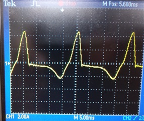
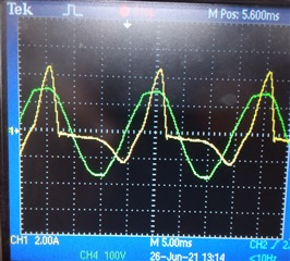
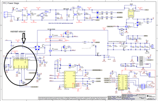
Actually I have designed a mother board taken reference from "the PMP20873 reference design" and in it there is no ct sensing and I am using it for running my 1kW bridgeless PFC following the TI PFC EVM code. Yellow one is AC input current and green one is input AC voltage(120V 50Hz). Testing it for only 100 W power, current is not in good shape. I would like to is this a tuning problem or some problem in firmware.
My PFC is not a totem pole bridgeless PFC, It is simply a bridgeless PFC but not ct sensed. I have used IC ACS716KLATR-12CB-NL-T to sense the input current.
So I would like to know since my bridgeless PFC is not a CT sensed, is any modification is required in TI PFC EVM code.
Hello, PMP20873 is a totem pole bridgeless PFC. You said your design is copied from PMP20873, then why it is not a totem pole PFC? What is your topology? Where did you put the hall sensor?
Hello, this is a totem pole PFC topology, the TI UCD3138 PFC EVM code is for traditional PFC, does not work on this topology, you need to write your own code for it.