This thread has been locked.

If you have a related question, please click the "Ask a related question" button in the top right corner. The newly created question will be automatically linked to this question.

BQ76952: Can I connect VSS to SRN instead of SRP

Part Number: BQ76952

Dear TI Team,

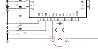
In my application I have a lot of peripherals on the same ground as bq76952's VSS and I need to take into account the significant current, being consumed my them, for coulomb counting. For this, is it advisable to connect VSS to SRN instead of SRP as in the image below? How would it affect current measurements and OCD/OCC/SCD protections?

Regards

Manuj 

  • Hi Manuj,

    Connecting VSS to the pack side of the sense resistor is common with many gauge devices.  It allows the BMS device to see the supply current and for a gauge, include that as a measurement rather than a compensation value.  The drawback of this connection is that large currents can push SRP and VC0 below VSS, both have limited recommended and ABS MAX ranges.  Cells designed for high currents can have significant SCD currents which could push SRP very negative. 

    The BQ76952 is expected to be used in systems with high power cells and significant SCD currents, so grounding at SRP is recommended.  The part is characterized with SRP at VSS.  Note the ABS MAX and recommended ranges for SRP, SRN, and VC0.  Consider these, the limits of other components in your design, and other system conditions as you consider other grounding approaches. 

    Signals may compress as you exceed the recommended operating range.  For example if you have an SCD level 100 mV with SRN at -150 mV and  SRP at -270 mV the part will not be damaged because ABS MAX has not been exceeded  but the SRP is outside its recommended range and it may take more differential voltage to achieve the SCD detection. 

  • Hi WM5295,

    • Given your explanation, I now plan to connect VSS to pack side (SRN) as I generally set SCD at 100mV. I have also probed between SRP-SRN and the short circuit current generally diminishes well within 200mV between SRP and SRN. Should I go ahead with the change of connecting VSS to SRN?
    • In your reply can you further explain this:  "For example if you have an SCD level 100 mV with SRN at -150 mV and  SRP at -270 mV". As per my understanding, since VSS will be connected to SRN; SRN should be considered to be at 0V and at 100mV SCD level SRP and VC0 should be considered at -100mV. This is different from what you have suggested in the example scenario.
    • After connecting VSS to SRN,  it is understood that there will be slight voltage fluctuations at VCO with respect to VSS when significant amount of varying current flows (because of the sense resistor in between). Will this create issue with cell voltage sensing? Are the cell voltage measurements differential? 

    Thanks and Regards

    Manuj

  • Hi Manuj,

    We recommend the VSS reference at the cell side of the sense resistor.  Connect the part as needed in your design.  Check for operation within the specified limits in all operating conditions.  If conditions stay within the recommended limits it should work fine.

    SRN at some voltage below 0V... Yes, ideally the connection of VSS is directly at the sense tap point so that SRN remains at 0 V.  In most practical layouts there is some trace resistance which results in some negative voltage.  This should be small.  The -150 mV example was meant to be extreme to show a potential mis-operation of the system with poor connection of the BQ76952 component.

    The cell voltage measurements are differential.  The cell voltages can measure slightly negative.  Section 16.2 of the data sheet includes the description "The recommended voltage range on the VC0 to VC4 pins extends to –0.2 V. This can be used, for example,
    to measure a differential voltage that extends slightly below ground,..." so yes it should measure properly if the movement is within the recommended range.