This thread has been locked.

If you have a related question, please click the "Ask a related question" button in the top right corner. The newly created question will be automatically linked to this question.

TPS65217: Application without battery; Problem with AC startup

Part Number: TPS65217

We are implementing a custom design inspired from Beagle Bone Black.

To avoid the brownout issue, we have implemented a circuit with voltage supervisor + load switch, and are facing issues during startup from external power supply.

To debug this issue, we are now trying to better understand the working of PMIC on batteryless applications.

Currently, we have removed the voltage supervisor and load switch from circuit, and applying external power supply directly to the PMIC input.

Can you please explain the differences between the below two scenarios?

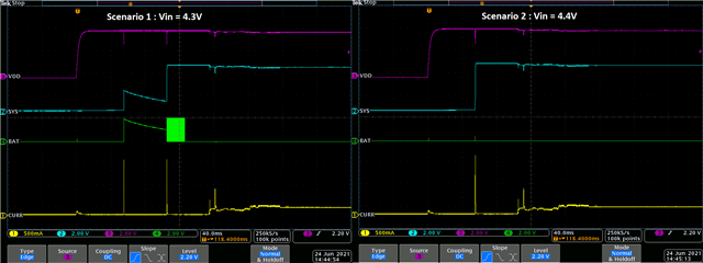
Scenario 1 : Vin = 4.3V

Scenario 2 : Vin = 4.4V

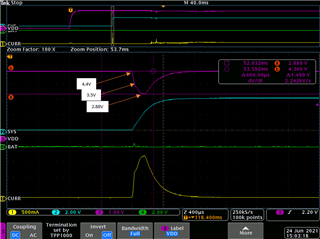
Question is, why is the SYS voltage not building up to full 5 V in one case, whereas it is building up to 5V in the other case?

With the voltage supervisor connected, this phenomenon of retry is worse. Hence we are looking to understand why this is happening in the first place.

  • Block diagram of the above experiment

  • Additional information.

    Minimum VAC voltage (dip) in scenario 1 = 2.84V

    Minimum VAC voltage (dip) in scenario 2 = 2.88V

  • Hi,

    Can you provide a schematic and layout of your design using scenario 1 (voltage supervisor and load switch)?

    Best,
    Emily

  • Hi, 

    Both the scenarios do not have voltage supervisor + load switch. It is removed from the circuit.

    In both the above 2 scenarios, Vin is given directly at the AC pin of PMIC.

    The two waveforms are for PMIC input directly connected to external supply, but with different input voltages (4.4V and 4.3V)

  • As per the datasheet section 8.3.9.1, 

    " the device powers up if the AC or USB input voltage increases above 4.3 V. After powering up, the input voltage can decrease to a value of VUVLO + VOFFSET (for example, 3.3 V + 200 mV) before the device powers down."

    Here in the attached figures, even when Vin goes < 3.5V, VSYS is building up. Is this expected phenomenon?

  • Hi, 

    Is this most recent waveform indicative of a scenario where VIN = 4.4V and so the system powers up, but as you decrease VIN, the device does not power down even at 3.5V? Is there a UVLO voltage that the device does appear to have to reach before powering down? 

    Best,
    Emily

  • Hello, the most recent waveform above is indicative of the scenario as described below:

    Input voltage given to PMIC is 4.4V. The inrush current demanded by the output capacitance connected to SYS pin (output of PMIC) causes the input voltage to at PMIC AC pin to dip to 2.88V for a transient duration.

    As mentioned in the datasheet, the voltage removal detection is 3.5V

    I can see that the PMIC is trying to turn off the linear power path switch from AC to SYS, as soon as the AC voltage drops to 3.5V.

    Question 1: Even when AC voltage drops lesser than 3.5V, why has the PMIC not turned off? Is there a deglitch time where it does not consider the voltage dip?

    Question 2: If there is a deglitch time, then why was it not applicable in the 4.3V (Scenario 1 image in the top). Here the PMIC has turned off.

  • Hello,

    There is a UVLO deglitch time of 4-6ms, so it's possible that if the AC voltage drops <3.5V less than the deglitch, it will not recognize this brownout.

    I am curious about the 4.3V Scenario you attached scope shots of though- why is there a voltage on VBAT that ramps up initially with the VSYS at all? If the only difference between the 4.3 and 4.4Vin scenario is input voltage, there shouldn't be any VBAT voltage if your system does not have a battery attach. It appears to me that there is not sufficient output capacitance close to the PMIC- VSYS startup appears to be choppy ramping up to 5V, which could indicate that the output voltage is exceeding the reference voltage. 

    Best,
    Emily