This thread has been locked.

If you have a related question, please click the "Ask a related question" button in the top right corner. The newly created question will be automatically linked to this question.

LM3410: Problem at startup (burned IC)

Part Number: LM3410
Other Parts Discussed in Thread: TPS563208

We are using the LM3410XMF for some years without problem in the same pcb and application.

For some months we have the problem that some IC´s fail at startup (burned IC) - (maybe here or in the field) and have to be replaced.

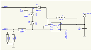
Input is: 3,3V, Output 1/4" VGA display with about 20V and 20mA LED voltage/current.

As the application is nearly 1:1 from the data sheet we have no idea what could it be, tried a lot without success.
At one chip i measured 500Ohm between Ground and Pin 1.

The LED_CTRL pin comes from a display controller who is powered by the same source on the same pcb.
PWM could be programmed, but is not activated at startup -> at startup the LM3410 has 3,3V on this pin.

Hope someone could help us.

  • Hello,

    Have any parts changed on the BOM?  Is the inductor the same one that has been used?  You have the overvoltage protection zeners on the design.  The most common failure is open load without the zeners causing damage to the LM3410.  Does the board fail on first power applied after they are made?  How are they first powered up?  With or without a load connected?  Are these boards repaired, if so what is replaced?

    Best Regards,

  • Hello,

    the inductor is a 10uH, 1.23A type (CDH53-100), the board failes not on the first power applied, but within the first startups. As our instrument is portable its switched on/off very often. We had one, failed at the customer the second time. They are powered with the LED load. Its always the same part we have to change, the LM3410. 

    Best Regards

  • Hello

    From the information I have I don't see anything that would cause this.  Is the input voltage stable?  How is is supplied?  The absmax on Vin is 5.5V it can be damaged if it goes above this.  Have you looked at the inductor current at power up?  The only other thing would be open LED however you have the two zeners to protect from that.  Absmax for the SW node is 26.5V.  I would look at the switch node voltage during power on as well just to see what it is doing.  How are the LEDs connected to the output as well as the output capacitor?

    Best Regards,

  • Hello,
    open LED is not the problem, LED is always connected, the OVP works well if i disconnect the LED output voltage is stable at 24V.
    The LED´s are connected to the output as well as the output capacitor. Input voltage is not the problem, it happens with two independant instruments. One is powered by a TPS563208 with 3,3V output (main supply) and there are a lot of other circuits powered by the same ic without problems, the other instrument uses a 5V 78M05 voltage regulator.

    I observed one time at startup that the LM3410 must become very hot (some smoke) but than worked normally.

    Best Regards,

  • Hello,

    The LM3410 draws a lot of current at startup to get to regulation, see figure 2 of the datasheet.  Is it possible that the power source is dropping during turn-on?  I would look at the input voltage at the LM3410 to see if it is able to start up without the input voltage dropping.  I would also look at the inductor current with an oscilloscope and SW node during start up to see if anything odd is happening.  I haven't seen a failure such as this, normally it is open LED failure without the zeners but you have that on this design.

    Best Regards,