This thread has been locked.

If you have a related question, please click the "Ask a related question" button in the top right corner. The newly created question will be automatically linked to this question.

BQ24616 part failure when connecting battery

Other Parts Discussed in Thread: BQ24616

Hello,

I have started testing a design using the BQ24616 battery charging IC. My design is identical to the typical application circuit in the datasheet for the part. I am having a problem that when I connect the actual battery, the part fails (with disastrous results). Everything works fine when I substitue a power supply for the battery. The only difference I can figure is that the battery has a much lower impedance and higher current capability than the power supply. So perhaps the BQ24616 can only handle a certain dV/dt? There is a small arc when I connect the power supply or the battery, which I assume is from charging the 20uF of capacitance on the "PACK+" line, and the 20uF through the MOSFETs on the "SYSTEM" line.

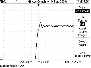
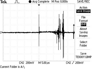
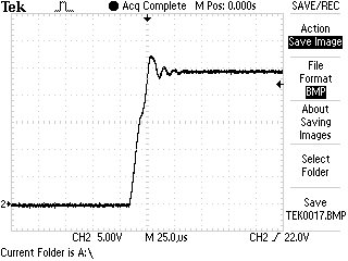
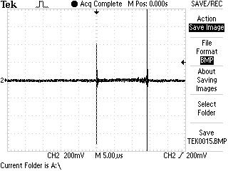
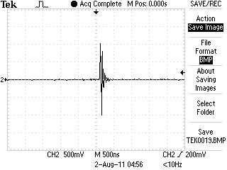
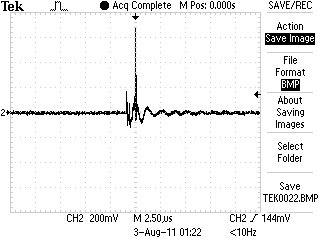
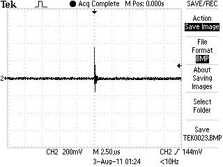
My battery voltage is 24V, and when I measure the "SYSTEM" line upon connection, I sometimes see spikes up to 35V. This is somewhat disturbing since the part lists 33V as the absolute maximum for most of its inputs. I am using a 6.8uH as shown in the example circuit. I noticed that there are direct connections to the part from both current sense resistors (ACN, ACP, SRP, SRN). Shouldn't there be some resistance on these lines? The PH line is also a direct connection. Those lines are the only high current paths I can see into the part that could cause failures like I've seen.

So far I have had two of these parts fail on me, and I don't want to continue troubleshooting until I can understand the problem. If anyone has some insight into this issue I would greatly appreciate the help.


Thanks,

Matt

Electrical Engineer

Zee Aero

  • Without soft start control, the system voltage could have a very high voltage spike. The voltage spike is related to the parasitic parameter (output wire parasitic inductance and output/system capacitanve and ESR). That is why the input have snubber and softstart control to prevent high voltage spike from input adaptor hot plug-in.

    In general, there is no problem in a notebook or netbook system. For example: input is 19V; output is 12.6V or 8.4V. Even battery hot plug-in, the voltage spike is not higher enough to damage anything.

    If the battery voltage is 24V, we have to be careful about the output wire length (parasitic inductance). That is why everything works fine until I substitue a power supply for the battery.

    Also, if we assume the parasitic inductance is A nH, the peak current is B Amp. The engergy in the wire is 1/2 x A x Bx B. You can put a TVS diode to absorb that energy.

    If it is necessary, we may have to add a soft start control for battery insertion.

  • Hi Wang,

    Thanks for the info. I put a 24V TVS diode between the top and bottom charge MOSFETs and GND. I also put one from the "SYSTEM" line to GND. That limited the voltage spike to about 28V. It seems to have fixed the issue. I will post here again if I have further troubles.


    Matt

  • I am continuing to have trouble with this part. I experienced another part failure on battery insertion. I am confused now as to what can be causing the problem. I have TVS diodes installed on the battery line and the adapter line. I have measured the voltage spike on battery insertion and it peaks at about 28V. This should be fine for the part to handle. Is there another failure mechanism besides over-voltage that can cause the part to fail? Is it sensitive to high dV/dt? My battery is very low ESR (~20mOhm) and my lead length is short (~6in).


    Matt

  • Yes. The SRP/SRN pin may be sensitive to high dv/dt.  The TVS doesn't need to put on the top and bottom FET.  Just put on sys and charger output.

    Also, Do you have any capacitor on SRP pin? When a 24V battery is plugged in, the SRP capacitor is charged through the current sense resistor. if the sense resistor has a high parastic inductance, it will generate a very high Vsrn-srp.  Please remove that SRP capacitor.

  • Here are some traces of battery connection:

    SRP to GND:


    SRP to SRN:

    SRP to GND with C10 and C2 removed:

    SRP to SRN with C10 and C2 removed:


    As you can see, the voltage spike on SRP peaks at about 28V and then settles to 24V. The voltage spike from SRP to SRN is bad with the SRP cap in place, but there is still a spike with the cap removed. The datasheet says the absolute maximum SRP to SRN voltage is +/- 0.5V. The spikes are exceeding this voltage. Do you think this could be causing the failure?


    When connecting the battery there is a small arc due to the extremely low ESR of the ceramic caps on the battery line. I am thinking about replacing the ceramic caps with tantalum caps. Would this be a possible solution?


    I should note that the failure is extremely intermittent. I have successfully connected the battery about 20 times with no failures. However I would like to understand the cause of the failure.

  • The output ceramic capacitor need to handle the output ripple current. The low ESR ceramic caps are put on the battery line. So, we can not change them all with tantalum caps.

    The voltage across SRP and SRN is clamp by the 0.1uF between SRP and SRN. If put that 0.1uF cap near IC, it can eliminate the high voltage spike. Please let that 0.1uF close to IC. Also, please keep SRP trace parallel with SRN trace on the layout. So, the parasitic inductance can be reduced.

    If the Vsrp-srn is too high (much higher than 0.7V), it may inject a high current to SRP/SRN pin and cause the damage.


  • I have followed all of the PCB layout guidelines in the datasheet. The 0.1uF cap between SRP and SRN is as close to the IC as possible, and the SRP and SRN traces are parallel (10mil spacing).

    You say the 0.1uF cap is used to clamp voltage spikes between SRP and SRN, so I just increased it to 0.2uF since I still was seeing spikes. However, after I did that and connected the battery I had a part failure. I captured the waveform when it failed:

    So you can see increasing the capacitance between SRP and SRN actually increased the voltage spike to 1V and caused a part failure. So maybe I should reduce the capacitance? 

  • The 0.1uF between SRP and SRN eliminate the switching noise on SRP/SRN pin. 

    The key is: Delete SRP cap first. If there is no current flowing from SRN to SRP during the battery insertion, the Vsrn-srp should be zero. After the SRP cap is removed, there is no current flowing to SRP (ignore the inductor parasitic cap and SRP pin cap).

    According to your test, the IC get damage after increasing the Csrp_srn. So, the cap between SRP and SRN gives a current path from SRN to SRP. That di/dt on SRP/SRN traces generate the Vsrn-srp. The 0.2uF may cause higher current from srn to srp. So, please keep it 0.1uF and make sure the  peak Vsrn-srp voltage lower than 0.7V.

    All our evaluation is done with 0.1uF cap across SRP and SRN. In your case, if the small cap can eliminate the switching noise (output current regulation is good), I think you can reduce it a little bit to help Vsrn-srp.

  • I changed the cap from SRP to SRN to 0.01uF and I still had a failure. The failure seems to be unrelated to the cap from SRP to GND or SRP to SRN.

    I decided to go back to the Evaluation Module and measure SRP to SRN on that. Low and behold after a few measurements I had a failure on the Evaluation Module!!!!

    Now I am convinced that I am doing nothing wrong, and that there is either a defect in the part, or the part is just not capable of operating at a 24V battery voltage. 

    I think TI needs to do some re-evaluation of this part and revise the datasheet accordingly. Now I am stuck with this part on my board, and I think the only interim solution may be to use an inrush current limiter on the battery line.

    Here are some traces of SRP to SRN on the Evaluation Module. The second one is when the failure occurred:

  • Is your battery a 5 cell in series configuration.

    Do you have big capacitor on battery + and battery - , if yes, you could add a series resistor of 1ohm or 2 ohm to it. Also you could try to have a TVS with clamping voltage greater than 25V and less than 27V with peak pulse power of 800W. You can add a fuse of about 1A in series to TVS to add protection to it

    The TVS need to be close to the battery connector in your PCB

    You need to watch out PH line as well. It can't go above 30V

    Use low inductance probes to measure such signals