This thread has been locked.

If you have a related question, please click the "Ask a related question" button in the top right corner. The newly created question will be automatically linked to this question.

LM25011: Calculation value Ton doesn't equal to the tested value

Part Number: LM25011

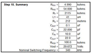
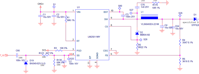
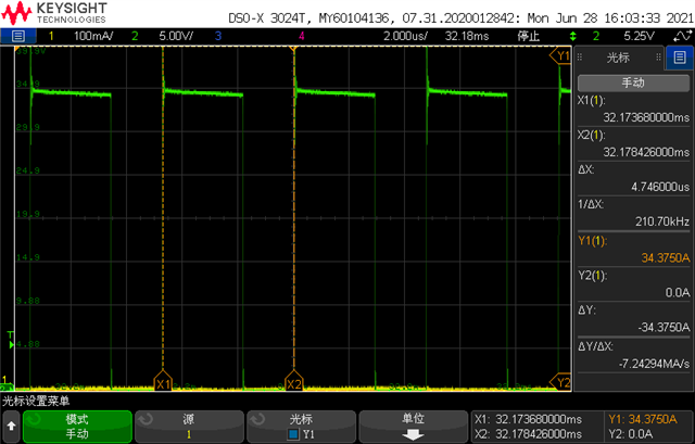
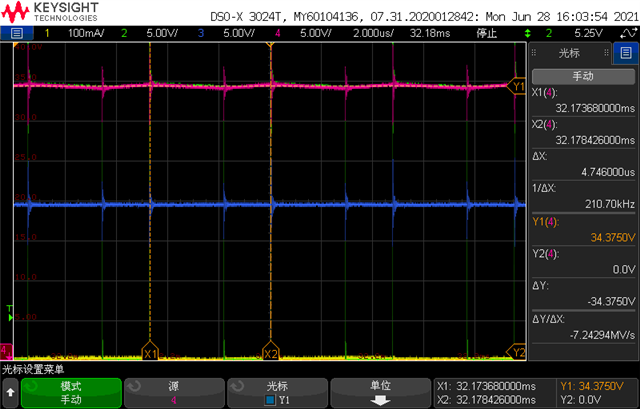
When calculating the Ton for LM25011, find there is a big gap between actual tested value with the calculation.

For example, Vin=34V, Rt=5.6M. Calculated Ton according to tON =(4.1 x 10⁻¹¹ x (RT + 500))/vin + 15 ns = 6.77uS. While tested value is 4.52us, and 2.89us(operating in current limit).

How much deviation between calculation and testing? 

  • Hi Mark,

    Can you please share all of the application conidtions? Vin, Vout, Fs, Iout? I would like to double-check the following calculations.
    40% of the test value, 4.52us, results ~2.7us which is relatively close to the tested 2.89us.

    Thanks,
    Alejandro

  • Hi iAlejandro,

    Vin is 34V, Vout is from 19.4v to 29.9v. Fs is from 210k to 340k. Iout is from 594 to 679mA. these are all tested value.

    I can understanding if Ton is 4.52us for normal mode, it will be 2.7us for current limit mode.

    While I can't understand the gap between 6.77us and 4.5us. This 6.77us is according to the formula tON =(4.1 x 10⁻¹¹ x (RT + 500))/vin + 15 ns = 6.77uS. That is a big gap with tested value 4.5us.

  • Strange.. Can you also provide a circuit schematic? I double-checked the calculations and they are correct. Below is a summary of recommended component values for the application requirements provided. The Quick Start Calculator tool (link) was used. I would like to review the circuit and make sure it is okay.

    Thanks,
    Alejandro

  • Hi Alejandro,

    The Rt value in our design is 5.6M. Not 2.115M.

    If calculating with Rt = 2.115M, Vin=34V, i can get a Ton = 2.566us.

    But in our application, Rt=5.6M, Vin=34V. Calculation result is 6.768us. While my test result is 2.7us. Even it is not at current limit mode, the tested value is 4.52us. This is a big gap.

  • Hi Mark,

    There might be some confusion, I want to make sure we are on the same page. So let's begin by ensuring the following:

    • Please provide a schematic for a review. We would like to make sure all is properly connected.
    • With an RT of 5.6MΩ it results a fsw of 130kHz, which does not correlate to what you provided of Fs equal to 210kHz to 340kHz (that's one point of interest).
    • Can you share waveform of on-time pulses along with output voltage and input voltage (preferably with cursors showing the time scale of pulses).

    Thanks!
    Alejandro

  • Hi Alejandro,

    Here is a schematic.

    Here is 2 scope. 

    Green is SW PIN. On-time is 2.89us. Fre=210k.

    Red is Vin=34.3v

    Blue is Vout=19.4v


    Since we are make it works at constant current mode. So the on-time is halved than that not in CC mode.

    BR / Mark

  • Hi Mark,

    Let me reach out to the team internally for further inputs. I will get back to you as soon as possible.

    Thanks,
    Alejandro

  • Hi Mark,

    We have not forgotten about this phenomena. Still waiting to hear back some feedback from rest of team. I will make sure to update you as soon as possible.

    Thanks for understanding! Kind regards,
    Alejandro