This thread has been locked.

If you have a related question, please click the "Ask a related question" button in the top right corner. The newly created question will be automatically linked to this question.

BQ79616-Q1: BQ79616PAPRQ1

Part Number: BQ79616-Q1
Other Parts Discussed in Thread: BQ79616, BQ76200

I have some queries regarding BQ79616-Q1, a 16-S automotive precision battery monitor, balancer, and integrated protector with ASIL-D compliance.

My queries:
1. How much time it will require to balance the 16 cells during charge and discharge?
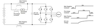
2. How we can implement contactor-based with this BMS?
3. What are the modifications we need to do hardware and firmware-wise?
4. As it supports bus bar connection and measurement. How can we measure the battery pack current?

  • Hello Padma,

    1. The cell balance can be configured based on the external resistors used in conjunction with the BQ79616-Q1 device up to a maximum of 240mA for 8 cells at ~75C. Please keep in mind that you can only balance odds or evens, so for you have this 240mA capability for the other 8 cells to consider as well. The time is dependent on the cell makeup so I can't comment on that.

    2. Can you please clarify what you mean in this question?

    3. This product supports many different battery pack configurations and so the hardware and firmware specifics are highly dependent on the use-case. We have example code and drivers to help customers get started with development with these products. 

    4. We have family products that include current sense capability. I would recommend looking into the BQ79656 which replaces the dedicated bus bar with a current sense ADC.

  • Thank you for the solution.

    Regarding the point 2 question, I would like to elaborate that the battery and the traction inverter are electrically isolated by main contactors.


    The main positive contactor is between the positive battery pole and the traction inverter while the main negative contactor is between the negative battery pole and the traction inverter.

    Both these contactors are required for safety robustness.

    The pre-charge contactor with a series current-limiting resistor is in parallel with the main positive contactor and used to charge the initially discharged DC link capacitor before closing the main contactors to avoid the high inrush current which might damage the battery, power contactors, and DC-link capacitor.

    My query is

    1. How we can implement contactor control in BMS?

    2. Can BMS control this contactor or we need to add an external MCU to control it?

    3. If there is a precharge circuit in BQ79616 & BQ79656?

  • Padma,

    Thanks for providing these additional details.

    1. I think overall, you need to use a MCU to control these contactors in the BMS system. The BQ79616 and BQ79656 devices can give the MCU details about the battery, but it does not have any specific features to address this contractor control.

    2. The BQ79616 and BQ79656 have GPIOs than could be used to control these contactors, but I think an MCU is probably the best solution.

    3. There is no specific circuitry for addressing the precharge circuitry inside the BQ79616 and BQ79656 devices.

  • Hello Alexander,

    Thank you for the solution.

    I'm quite clear that BQ79616 and BQ79656 EVMs don't have a precharge circuit. We need to implement it along with dc contactors externally using a separate MCU.

    1. Can we add BQ76200 which provides protection by controlling CHG and DSG high-side NMOS FET drivers and pre-charge PFET drivers?
    2.  Regarding firmware, we need software documents that include APIs and drivers with the help of which we can develop our application which is applicable to both BQ79616 and BQ79656.
    3.  How can we load firmware and upgrade it?
    4.  If OTA is supported?
    5.  Programmer and debugger device to be used?
    6.  Software tools and IDEs recommended to develop the application?
    7.  Please suggest MCU be used with CAN support?
  • Hello Alexander,

    Thank you for the solution.

    I'm quite clear that BQ79616 and BQ79656 EVMs don't have a precharge circuit. We need to implement it along with dc contactors externally using a separate MCU.

    1. Can we add BQ76200 which provides protection by controlling CHG and DSG high-side NMOS FET drivers and pre-charge PFET drivers?
    2. Do BQ79616 and BQ79656 support LTO cells?
    3. Regarding firmware, we need software documents that include APIs and drivers with the help of which we can develop our application which is applicable to both BQ79616 and BQ79656.
    4.  How can we load firmware and upgrade it?
    5.  If OTA is supported?
    6.  Programmer and debugger device to be used?
    7.  Software tools and IDEs recommended to develop the application?
    8.  Please suggest MCU be used with CAN support?
  • Hi Alexander,

    I'm waiting for your inputs on the queries. 

  • Padma,

    TI does not provide full system solutions for these applications. My team produces semiconductor components BQ79616 and BQ79656 and can respond to questions related to these device. I think the majority of your questions are outside of the scope of what I can assist with.

    2. Do BQ79616 and BQ79656 support LTO cells?

    There is no feature in these devices that specifically address LTO cells.

    3. Regarding firmware, we need software documents that include APIs and drivers with the help of which we can develop our application which is applicable to both BQ79616 and BQ79656.

    There is example driver code that can be downloaded through MySecure. https://www.ti.com/licreg/docs/swlicexportcontrol.tsp?form_id=305269&prod_no=BQ7x61x-Q1_DEVELOPMENT&ref_url=app_bms_bms-bap

    I can't really address the other items as they are very system or MCU specific.

  • Hi Alexander,

    Thank you for your inputs on my queries.

    I can understand some of the queries cannot be addressed and that's ok for us.

    Thank you very much for your time.