This thread has been locked.

If you have a related question, please click the "Ask a related question" button in the top right corner. The newly created question will be automatically linked to this question.

LM7480-Q1: Disabling Reverse Current Protection

Part Number: LM7480-Q1
Other Parts Discussed in Thread: LM74800-Q1

Hi,

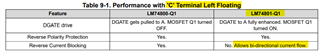
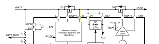
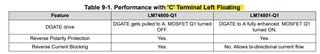
I am designing a power supply with battery charge and discharge functions. I need to cancel reverse current protection of LM7480-Q1 thus allowing bi-directional current flow., and still maintaining on/off control and reverse battery voltage protection.

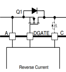
Can you confirm if using the part LM74801-Q1 instead of LM74800-Q1 + leaving the "C" pin floating + using common drain configuration works for my project.

Best Regards

  • Hi Olus,

    Yes, you are right.

    LM74801-Q1 in common drain configuration can allow bi-directional current flow when the "C" pin is left floating.

  • Hello,

    How can be the hardware if i want to switch current direction modes. And can you share the internal structure of pin "C" ?

  • Hi Olus,

    What do you mean by 'switch current direction modes' - do you want to enable and disable the bi-directional current flow by connecting and disconnecting the C pin to drain of the FET ? This can be achieved by connecting a logic FET (and control it using an external control signal) in between the C pin and the drain of the FET. 

    Unfortunately, we cannot reveal the internal structure of pin "C". The voltage across A-C is continuously monitored and the gate is controlled accordingly as described in the datasheet. 

  • As we don't know the internal structure, i have to ask if leaving this pin without any connection ( pull-up, pull-down etc) causes any problems, especially in terms of susceptibility tests ? Do we need a capacitor, resistor, tvs etc on this pin for some protection ?

    To switch between current direction modes, should it be bi-directional switch on pin "C", if not what should be the direction ?

  • Yes, you can leave the pin floating without any issue. This is also specified in the datasheet as shown below.

    Since the current always flows into the C pin, we can use a logic FET to disconnect it in the orientation shown below to disconnect it. Alternatively, you can use a BJT in place of logic FET to block bidirectional current (from and to C pin) when turned OFF. 

  • This information will be useful. Thank you for your support...