This thread has been locked.

If you have a related question, please click the "Ask a related question" button in the top right corner. The newly created question will be automatically linked to this question.

UCC21750: Undershoot in gate pulse

Part Number: UCC21750

Hi

We have used UCC21750 to switch our Synchronous Buck MOSFET

We are getting under shoot in the gate pulse of top MOSFET as the below image(Fig:1)
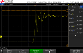
Fig:1

We have used 1E for RON and 0.3E for ROFF

Our Mosfet details in (Fig:2)
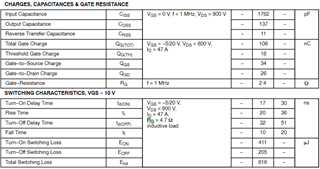
Fig:2

Need your support to solve this issue

Please share your mail ID to take this conversation as a personal conversation

  • Hi,

    Before taking the conversation to email I have a few comments/questions on what the issue could be:

    1. Probing
      1. Having a large probing loop affects the amount of noise that appears on the scope. To get the most accurate representation of the gate signal use a small probing by using a "pigtail". The pigtail connecting to the reference point (COM), and probe tip on the gate net. (Probe with Pigtail shown below)
    2. Gate loop + external gate resistance
      1. In the gate driver loop, there are parasitic inductance which can resonate with the parasitic capacitance of the power switch and cause oscillations, especially when the gate driver internal resistance is small. In this scenario, the gate drive external resistance can help damp the oscillation and should be designed based on the parasitic components of the gate driver loop.
        1. From a layout perspective the parasitic inductance can be reduced by creating a smaller gate loop (Gate driver output to MOSFET gate, and MOSFET source to gate driver COM-pin)
        2. Increasing gate resistance will also mitigate the ringing on the gate, but will increase switching losses. This trade-off will have to be balanced based on your system requirements.

    If you have further questions and or comments you can continue commenting on this thread or send me an email. I have shared my information via direct message through this E2E forum.

    Best regards,

    Andy Robles

  • Hi

    Thank you for the response

    1. We are using the same probe setup to capture the gate pulse as in (Point 1.a)

    2. (Point A). For the layout we have followed as per the datasheet which match your comments 

        (Point B). We have increased the RON value upto 10E. we have observed there is change in the Gate pulse    overshoot and dip but the switching loss is more as you mentioned  

    We have used the same MOSFET and drive for the Bottom side, but we didn't observe these issues in Bottom side 

    We have checked the topside driver supply but there are no issue in the power supply.

    Need your support to proceed further

  • Caliber,

    As you mentioned, this is a buck converter, the high side MOSFET is hard-switched and low side MOSFET is soft-switched. When you measure high side MOSFET gate-source voltage, I assume you used a differential probe. Please check which probe you used and what's the CMRR. Part of the overshoot/undershoot is likely caused by the common mode dv/dt across the differential probe.  No overshoot/undershoot is observed for the low side MOSFET gate, this is due to: 1) low side MOSFET is soft-switched; 2) no common mode dv/dt for the probe.

    Regards,

    Gangyao