This thread has been locked.

If you have a related question, please click the "Ask a related question" button in the top right corner. The newly created question will be automatically linked to this question.

UCD90320: watchdog timeout error

Part Number: UCD90320

Hello Guys,

Good day.

Our customer is using the UCD90320 power sequencer on their design.  He was in the process of writing a new config into the part on one of the boards when the power was interrupted.  After getting the power back, he plugged in the TI cable and used the Fusion software to load the new config into the part.  In this design he use one of the GPIO to turn the power on and off.  Now on that board when he turn the power off and then back on using the GPIO pin, he get a watchdog timeout error when he set the GPIO to on and the UCD goes through ~50 resets before the UCD will enable the POLs.  He have tried erasing the part and reprogramming it several time but he can't seem to get this behavior to stop.  Note that he don't have any watchdog timers enabled in his design. Also note that none of his other boards exhibit this behavior.

Does it mean the firmware was corrupted? Is it possible to provide firmware to the customer?

Thanks and regards,

Art

  • Hi 

    I would suggest them to check the GPI signals into the UCD90320. I suspected at last one of the GPI single of UCD90320 are under fast toggling.

    Regards

    Yihe

  • Thanks Yihe. I'll notify customer about this. In case they need the firmware, is that something we can provide?

    Thanks and regards,

    Art

  • Hi

    I do not think it is related to the firmware. Noisy GPI signals most likely are the root cause.

    We can provide firmware if it is indeed the issue.

    Regards

    Yihe

  • Hello Yihe,

    See below response from the customer.

    "In my design the only regular GPIO that I use is C9 which I use as an output that turns on an LED when the power sequence is complete and the power is on.  I don’t see this LED turn on until after all the resets finish and the UCD finally does complete the power sequence.

    I also use six of the DMON(GPIO) pins as digital voltage monitors that monitor the power good signals from some of my POLs.  These pins are F4, F3, G3, D10, L11 and N12.  I have checked all of these pins and I don’t see them toggling until the power sequence actually runs.

    I use another of the DMON(GPIO) pins N11 as my enable/disable pin.  I have been monitoring this pin and it only toggles when I tell it too and when it toggles the signal is monotonic."

    Thanks and regards,

    Art

  • Hi

    In the original description, it said that the UCD went through ~50 reset when he used the GPO to turn on the power. 

    So the problem is only present when the power is on. the DMON is also part of the GPI for the UCD90320. if the PG is toggling at fast pace when the power is on, it may flood the device. Could they probe the DMONs to see which one has fast toggling? or they can remove the DMON from the configuration file one by one to isolate the issue?

    It is also helpful to debug if they can provide the configuration project file and schematics 

    Regards

    Yihe 

  • Thanks Yihe.

    I'll inform customer about this. Also, I might direct customer to this link so that they can explain the scenario better.

    Thanks and regards,

    Art

  • Hi

    Sure, they can also share the project file and schematics to help debug.

    Regards

    Yihe 

  • Art

    I uploaded the schematic page that contains the UCD90320 to the original thread.  I did not upload the config file because I was not sure if you wanted the .tisp or the .xml file.  

    Note that I did scope all of the GPIO pins and none of them are toggling as yihe had suggested.  Can you please supply me with the firmware file so that I can try and reprogram the firmware to rule that out as a cause?

    Thanks

    Rob

  • Hi 

    There was no schematic page on the original thread. Could you repost it? Please provide .xml file. 

    I do not think it is firmware related. if firmware is wrong, you can not communicate with it via I2C.

    Regards

    Yihe

  • Yihe

    I posted it to my original conversation with Art.  I didn't post it here because I was not sure if this thread was public or private.  My assumption was that the trouble ticket that started my thread with Art was private but I was not sure if this thread was on the public forum.  I also posted the .xml design file. 

    Rob

  • Hi

    It is public forum. You can ask Art to forward the files to me.

    Regards

    Yihe

  • Hello Yihe,

    I just sent the requested files to your email.

    Best regards,

    Art

  • Hi

    Thank you, I will review it and let you know.

    Regards

    Yihe

  • Hi 

    I had reviewed the project file and schematics. The project file is working well on UCD90320 EVM. Of course, EVM does not have the power rails as in your board. But this tells that the configuration does not cause problem. 

    There is no decouple cap(1nF) on the RESET pin. we recommend a 10k + 1nF on the RESET 

    Do you see the same issue on other board with the same configuration so that we can know it is specific board related. 

    In the original post, you mentioned that the device reset 50 times only when using GPIO to turn on the power. i assumed that the GPIO here is the pin N11. Could you please confirm?

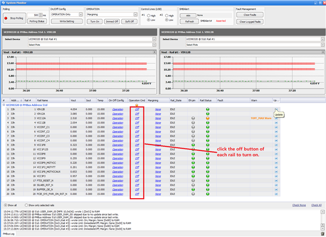
    As you had confirmed that pin N11 or other DMON pis are not toggling randomly or with noise. I would like to try the following: instead of using pin N11 to turn on all power at the same time, please use the OPERATION COMMAND to turn on rails on by one. in this way, you can know which rail caused the problem.  please be ensure that N11 is LOW during the test. 

    here is the snapshot of how to use system monitor to manually turn on rails one by one.

    Regards

    Yihe

  • I am assuming that in order for that to work, I will need to go into the configuration and on the "Global Configuration" tab on the "Pin Selected Rail States" screen I will need to uncheck the "Enabled" boxes for the "Pin Selected Rail States Config".

  • Yes, I have used this configuration file on a number of boards with no issues.  I only have issues on this one particular board.  On the normal boards I don't ever see the reset count increasing when I toggle the enable pin off and on.  I only see the reset count increasing on this one particular board that seems to be corrupted.

  • Hi

    No, you do not have to and just leave as is. The key is to ensure that N11 is LOW all the time.

    Regards

    Yihe 

  • Turning the rails on one by one using the GUI all the rails powered up correctly.

  • Hi

    For me this particular boards have some cross talking, since turn on or off power shall not impact the UCD90320. 

    The theory is that when some rails are ON, it may impact the VCC or RESET of the UCD90320 since you had confirmed there are no toggle on all INPUT signals. 

    Regards

    Yihe

  • Can you just send me the the firmware file so that I can reprogram the firmware and rule out that possibility?

  • Hi 

    Let me check with Art on this.

    Regards

    Yihe

  • Hello Yihe,

    The case can be close now but unfortunately customer is not sure exactly what fixed the issue.  He reprogrammed the firmware and that seemed to make it a bit better but didn’t fix the issue.  He then took the PCB out of the system and put it into a test chassis.  In that chassis he reprogrammed the firmware as well as the configuration file then power cycled the board.  The board seems to have started to work so he put it back into the original chassis and the board seems to be working now. 

    Thanks and regards,

    Art

  • Hi 

    Thank you for the update. The firmware has nothing to do with it. maybe there are some connections issues between the PCB and system. Please report back if they are able to reproduce the issue.

    Regards

    Yihe