A related question is a question created from another question. When the related question is created, it will be automatically linked to the original question.
If you have a related question, please click the "Ask a related question" button in the top right corner. The newly created question will be automatically linked to this question.
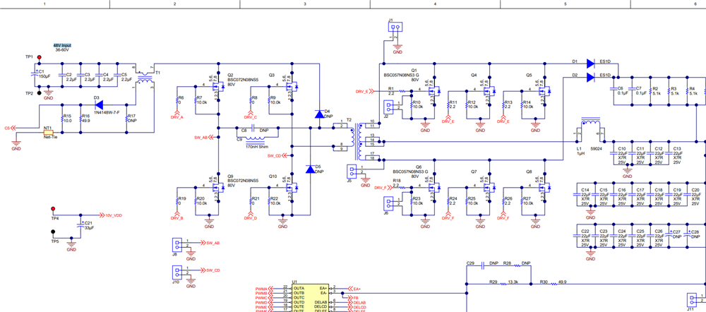
UCC28951-Q1: significance of primary side diodes D4 and D5
Those diode provide a path for the difference in primary transformer current and the shim inductor when the design comes out of freewheeling.
If you do not have these diodes this extra current will cause excessive voltage across the primary of the transformer; as well as, your secondary FETs.
These clamping diodes are necessary for the phase shifted full bridge controller to operate correctly.
While selecting these diodes as I can see its voltage rating must be similar to that of primary side MOSFETS. what about the current ratings of these diodes . I cant be able get a clear picture of average current rating of these diodes ??
To select these diodes I would select them so they can handle the primary peak current of the Hbridge. You could set the RMS current to be similar to the primary H Bridge FETs. Most design
I gave this some thought. The current going through the diode when the transformer is first energized should be the difference in reflected output current ripple.