This thread has been locked.

If you have a related question, please click the "Ask a related question" button in the top right corner. The newly created question will be automatically linked to this question.

TPS61021A: limit startup current

Part Number: TPS61021A

Hello TI team,

I'm working on a low power application using a TPS61021A.
To save power I turn on/off the TPS61021A often.

The device is battery powered (AAx2) and if the batteries are below around 40% charge, the voltage drop caused by the TPS61021A startup current is a problem.
I've lowered the output capacitor and increased the input capacitor but it's not enough.

To further limit the startup current I'm considering two ways :

1. Enabling the TPS61021A gradually

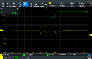
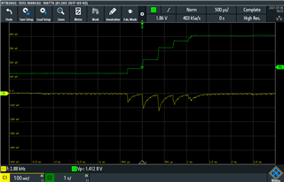
I pull the EN pin high for around 80us then low  then high again until reaching the nominal output (4V).
This method seems to be working well.
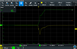
On the graph below green is TPS61021A  output and yellow the voltage drop on the battery. Voltage drop is limited to around 100mV compared to around 350mV with a regular startup.


Is this method reliable enough for high volume production ?

2. Using a RC circuit on Fb pin

The method is described here : https://www.ti.com/lit/an/slva307b/slva307b.pdf

I tried it but the results are not as good as the first method. It seems that the first startup phase (output capacitor charging) is not impacted.
Does the note slva307b applies to TPS61021A ?

Thanks for your help
Guillaume


  • Hi Guillaume,

    Thanks for using our device and study the device in such depth. I have my comments below for your two methods:

    1.Enabling the TPS61021A gradually:

    The delay between EN pulls to HIGH and TPS61021A can regulate the VOUT is unspecified. This may work, but something should be noted. 1st to noted is there should be very light load on VOUT. And 2nd is how long between EN pulls LOW and device stops switching is also not specified. How long the EN HIGH duration will also influence the drop of VIN in start-up, but it is controlled by you.

    Based on two points above, it is hard to say no problem for this method.

    2.Using a RC circuit on Fb pin

    The extended soft-start time will influence the phase after pre-charge. The pre-charge phase would not be influenced by external SS circuitry, because switching frequency and current limit is internally controlled. The input current will be influenced by external circuitry after this precharge phase.

    My recommendation is you can add more input cap and add external SS circuitry at the same time, let the input survive the pre-charge phase. Then the external SS circuitry would work and lower down the current from input.

    Let me know your thoughts. Thank you!

    -Wenhao

  • Hello Wenhao,

    Thanks for your reply.

    Following your advice I added more input capacitance and improved the external SS circuitry.
    This allows to reduce the drop to around 200 mV without using the first method ( yellow is voltage drop on battery and green is TPS61021A output):


    200mV is still a bit high but almost acceptable.

    So I also implemented the first method to decrease the voltage drop due to the pre-charge phase. I understood it's not fully reliable because delay between EN high and regulation is unspecified but the method can't be harmfull. At worst the precharge phase is unchanged.

    If you have any information regarding the variablity of the delay specified above that would be helpfull.

    Thanks for your help
    Guillaume

  • Hi Guillaume,

    Sure I will check this delay with design. Let me get back to you later next week.

    -Wenhao

  • Hi Guillaume,

    After checked with design, in the 25C normal temperature, the EN delay is about 20~30us. In lower temperature it will be much longer, about 200~300us. It mainly depends on internal  reference delay. We cannot guarantee the EN delay. Thanks!

    -Wenhao

  • Hi Wenhao,

    Thank you for this information, it will be useful to us.