This thread has been locked.

If you have a related question, please click the "Ask a related question" button in the top right corner. The newly created question will be automatically linked to this question.

UCC28950-Q1: Delay settings testing

Part Number: UCC28950-Q1
Other Parts Discussed in Thread: UCC28950

Hi E2E,

Good day.

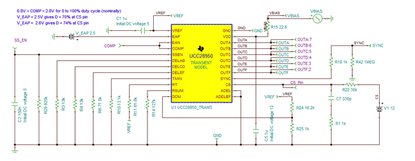
Our customer would like to test the different delay settings in the UCC28950-Q1 without the power stage configuration. Are all pins necessary to be connected? What pins can be left floating or connected to the ground? The customer would like to know how the controller and especially the delays behave under certain temperatures.

Regards,
Carlo

  • Hi, Carlo

    UCC28950 can be running in open loop mode, you can use below configuration as reference.

    Yunsheng

  • Hello Yunsheng,

    Is this a transient model from Pspice? Are the transient models from Tina and Pspice the same? or what is the difference? Can you please share the reference for that circuit?

    Thank you.

    Regards,
    Carlo

  • Hi, Carlo

    the transient mode is different for PSPICE and TINA since they are different simulation tool. The simulation model team design different model for PSPICE and TINA. 

    The circuit I shared with you is an open loop example which edited in TINA. 

    You can design the open loop circuit or board based on that. 

    Yunsheng

  • Hello Yunsheng,

    In the sample configuration you've provided, a 12V supply voltage is connected to the CS pin. In the datasheet that CS pin should not exceed 2V. Could you please explain, why there is this 12V supply at CS Pin?
    Regards,
    Carlo

  • Hi, Carlo

    there is C7 and R1 on CS pin, the 12V supply voltage is charging CS pin voltage through R22+R1.

    and there is an internal 200-Ω pull down MOSFET at the CS pin which is turned on immediately after the PWM comparator has tripped and OUTC or OUTD goes low. The pull-down helps to set the CS signal back to zero prior to the following switching cycle and reduces the time needed to reset the PWM comparator to make it ready for the next switching cycle. 

    So the waveform on CS pin with the configuration I send to you is sawtooth wave.

    Yunsheng