This thread has been locked.

If you have a related question, please click the "Ask a related question" button in the top right corner. The newly created question will be automatically linked to this question.

LM5176: On the problem of large standby current when lm5176 is no load

Part Number: LM5176
Other Parts Discussed in Thread: LM5175

Hi, Ti engineer!

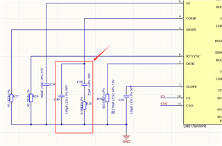
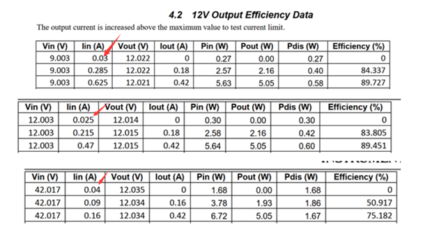
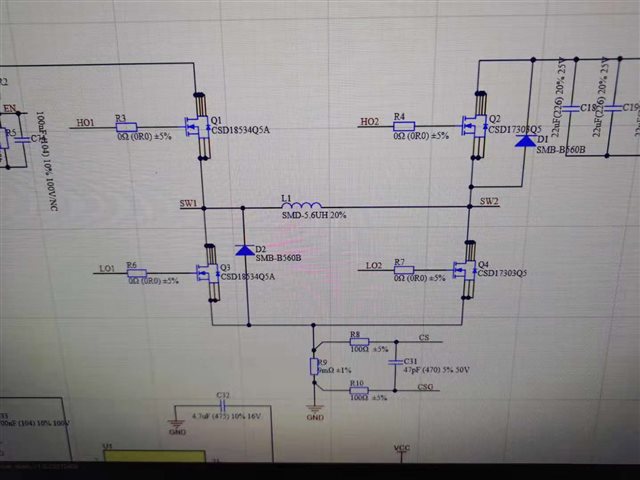
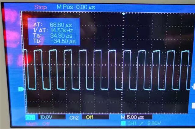
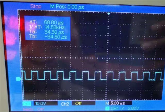
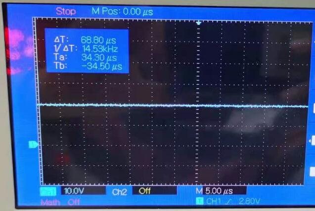
At present, I use lm5176 to design buck-boost circuit, input 8 ~ 36V, output 12V / 6A, switching frequency 200kHz. At present, the test circuit is basically normal, but when the output is not connected to the load, when the input is 24V, there will be 70ma no-load current.I suspect it is the inductance problem. I replaced an inductor with the same package and inductance (inductance: 5.6uh), and the no-load current was reduced to 40mA.

I think the no-load current is still a little large. How much of the no-load current is normal? What aspects can we start from to reduce the no-load current. thank you!

  • Hi Sheng,

    you are right, this no load current is really to high.

    Can you check that the condition in the datasheet 7.3.13 Gm Error Amplifier  ( V Comp limit ) is met on your board.

    Can you check that there is no component on your board which lead to this high bypass current. Maybe a Capacitor did see an overload and got damaged.

    May you can also check your switching nodes - they should be in pulse skipping mode and show very long pauses between the the pulses.

    Best regards,

     Stefan

  •  thank you! Stefan!

    As shown in the figure above, it is necessary to adjust the value of resistance and capacitance in the red box?

  • Hello Sheng,

    yes, this needs to be adjusted based on your configuration. You can find details about the calcuation in the Datasheet at 

    8.2.2.14 Frequency Compensation

    You can also use the LM5176 Design Calculator which can be found on the product page: LM5176 data sheet, product information and support | TI.com

    Best regards,

     Stefan

  •  thank you! Stefan!

    The figure below is the official data sheet of lm5175. The first item is whether I can think that there is tens of ma current when no-load. Is this normal? So lm5176 should also have this current. How much is the no-load current?

  • Hello Stefan!

    I tested the input of 24 VDC and output of 12 V without any load. At this time, the input current is about 40 ma.As shown in the figure below, it is the bridge arm part.

    As shown in the figure below, it is Q1 waveform

    As shown in the figure below, it is Q3 waveform

    As shown in the figure below, it is Q2 waveform

    Q4 off.Lm5176 works in Buck mode.As shown in the figure below is the reference waveform of snvu547. The above waveform is the same as this one. So I think work is normal.

    In the actual circuit, the heating of IC and MOS is very small, only inductor heating, but the temperature is not very high, about 30 degrees.

  • The temperature is between 35 and 40 degrees!

  • Hello Sheng,

    LM5176 does not have a power save mode. So even during no load it is permanently switching. As the power stage is typically optimized for medium to high output power, the losses in the MOSFETs and inductor will cause this quiescent current when the system is not loaded.

    The advantage of no power save mode is a fixed switching frequency independent of the load current, the disadvantage is higher quiescent current.

    Best regards,
    Brigitte

  • thank you! Brigitte!If lm5175 is used with low power, the loss is small?

  • Hello Brigitte!

    Does Ti have a buck-boost power chip similar to lm5176 with power of about 100W. If there is frequency conversion control in light load or small current, it is best. I need 8 ~ 24 V input voltage and 12 V / 6 a output voltage.