This thread has been locked.

If you have a related question, please click the "Ask a related question" button in the top right corner. The newly created question will be automatically linked to this question.

LM5072: Reduce output ripple for fast transient of dynamic load

Part Number: LM5072

Hello,

We have an 802.3at PD design by using LM5072-80. The design is a flyback design with output of 12V/2A.

It is working well with small output ripple (< 60mV)  in static load. However, the output ripple is large than

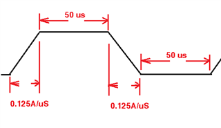
1V when the PD is loaded with an Electronic Loader which was setting with fast transient (125mA/us).

The PD has been equipped with a "LC low pass filter" at output port. 

Is there any way to reduce the output ripple for dynamic load? Is this large ripple related to poor bandwidth,

or it is unstable at fast load transient? Should I fine tune voltage compensation loop?
Best Regards,

David

  • Hello David, 

    A larger ripple is expected with a load transient. There will always be an overshoot, so that is normal.

    There are a number of contributing factors that affect the load transient response. The easiest to fix is the amount of output capacitance. Try to increase the output capacitance. However, when the output capacitance is increased, it decreases the bandwidth. Therefore, you may to adjust the feedback loop at the same time to compensate for the increased capacitance. 

    The following paper will aid in the compensation adjustment:

    https://www.ti.com/seclit/ml/slup340/slup340.pdf 

    If this post answers your question, please indicate so by marking this thread as resolved. Thank you.


    Regards, 


    Michael P.

    Applications Engineer

    Texas Instruments 

  • Hi Michael,

    Thanks for your reply. We tried to use electrolytic capacitor (330uF/25V) from different venders,

    and we got different results. The C7 from one of vender, have larger ripple (220mV) @12V/2A static load,

    yet it has smaller ripple (550mV) @12V/2A dynamic load. The setting of dynamic load is shown in 

    my original question. However, the C7 from other venders, have smaller ripple (60mV) @12V/2A static load,

    and they cause larger ripple (1.83V) @12V/2A dynamic load. 

    Is the large output ripple caused from closed loop stability? If so, the ripple may be able to be improved

    by fine tuning type-II compensation. Should I increase the value of R18 or C18  in order to decrease the zero of compensation loop? Or, it is because of slow output transient response (Bandwidth too small)?

    Besides, the electrolytic capacitor C7 (330uF/25V ) is located in front of output LC filter,

    I am not sure if it plays the role of output capacitor or not? Nevertheless, its ESR seems to affect the output ripple. The output capacitor C9 (10uF) is a MLCC, so it has low ESR.  Nevertheless, its output ripple @dynamic load is unacceptable.

    Since the C7 supplied by first vender is to be End-of-life. Your kindly reply is appreciated.

    Best Regards,

    David

  • Hello david, 

    The difference in performance between the vendors is most likely due to the difference in ESR ----- this is assuming they use the same material for the capacitors and have the same size and same ratings. 

    The ESR of the capacitor plays a role in the feedback loop.

    I would try increasing the output cap on the output of the inductor. Additionally, are they any ceramic caps on the output? You could insert some 1uF and 0.1uF caps to help filter. 

    Increasing R18 will shift a zero to a lower frequency, but it also shift a pole to a lower frequency (the pole created with C21). To get a similar affect without changing the pole, try increasing C18. 

    I will say, it is difficult to determine the exact values of the feedback without a bode plots. This will show us the bandwidth, the gain and phase margins. this will confirm if the system is stable or not. 

    Are you able to provide these?

    If this post answers your question, please indicate so by marking this thread as resolved. Thank you.


    Regards, 


    Michael P.

    Applications Engineer

    Texas Instruments 

  • Hi Michael,

    Thanks for your reply. The output capacitor after inductor, C9, is a MLCC. All the electrolytic capacitors we tried , C7, are same specification, except with a little bit difference in ESR. I don't have tester to generate body plot on hand. However, I will try to increase the output capacitor C9 first. If I still get large output ripple, I will try to measure output ringing to fine tune the compensation loop.  

    Best Regards,

    David