Hi,
My thread is locked so I post a new thread. I have some trouble on several boards. I don't understand three points :
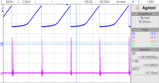
- why COMP signal (blue curve) increases to a 1.9V level,
- why LM3488 begins in continuous conduction mode even without load,
- why it stay in continuous conduction mode with the load (solenoid valve).
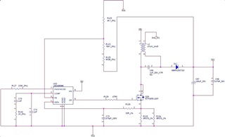
Schematic :
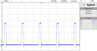
Curve 1 (COMP signal in blue + DR signal in pink) [board KO]
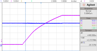
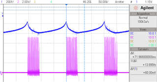
Curve 2 (COMP signal in blue + DR signal in pink) [board OK]
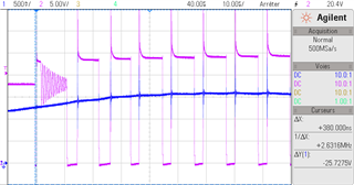
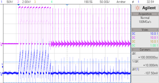
Curve 3 (DR signal in pink + ISEN signal in blue [peaks in discontinuous mode is just a ground cable length too long])
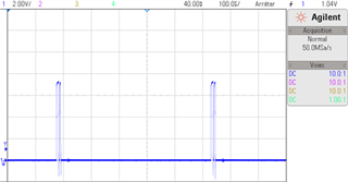
Curve 4 (DR with load [board KO])
Curve 5 : (DR with load [board OK])