This thread has been locked.

If you have a related question, please click the "Ask a related question" button in the top right corner. The newly created question will be automatically linked to this question.

BQ24650: Question for datasheet

Part Number: BQ24650

Hello,

Based on datasheet of below

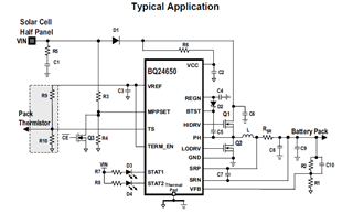
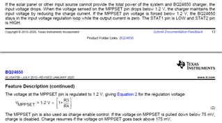
1) From my understanding, Vmppset = VIN * R4 / (R3+R4), which is not as below equation 2, please clarify.

2) scenario,  is below understanding right? What's difference of 2.2) and 2.3)?

      2.1) Vmppset > 1.2V, the charge current; 

     2.2) 75mV< Vmppset <1.2V, output current = 0;  

     2.3) Vmppset < 75mv, charge disable.

  • Hello,

    1) The V_MPPSET isn't the voltage at the MPPSET pin when regulated. That voltage is 1.2 V. Equation 2 describes how to use the resistor divider to determine the programmed MPPT voltage, known as V_MPPSET. This is the voltage that the input is held at if the solar panel becomes overloaded. If 1.2 V = R4/(R3+R4)*V_MPPSET, then V_MPPSET = 1.2 *(R3+R4)/R4 or 1.2*(R3/R4+1). Program the divider accordingly.

    2) Observation 2.2 is incorrect. If the MPPSET pin falls below 1.2 V, it will continue to regulate the input voltage at the programmed MPPT voltage. This means it will reduce the output current in order to maintain the input voltage. If however the MPPSET pin falls below 75 mV, then charge is disabled until MPPSET goes above 175 mV again.

    Thanks,

    Mike Emanuel

    Please click "Resolved" if this answers your question.

  • Hello,

    I don't use any solar panel in my application. 

    I will use power adapter = 12V connecting at VIN. 

    So, should I calculate 12V * R4/(R3+R4) = 1.2V?

    Then I set R3 = 180k and R4 = 20k

  • Add more question,

    1) How to select D2? What's the working voltage of BTST?

  • 1) should we need 1W resistor for input using 12V power adapter to charge? How the power calculated here?

    2) I am not sure how below value calculated. Can we combine the resistor value and capacitor value to common value, such as 2ohm + 2.2uF or 10ohm + 1uF?

  • Hi,

      Set MPPSET voltage to a level below the actual operating voltage of your adapter. You don't want normal operating condition to always be in input voltage regulation loop. REGN charges BTST capacitor when LSFET is on. You can select similar operating conditions for BTST diode as the one used in the EVM schematic shown in the user guide.

    RC is used to mitigate input voltage overshoot on adapter plug in. As the initial current can be large, R package has to be sized appropriately for power dissipation when charging C1 during plug in. RC circuit is optional for use depending on system.  

    Yes, use 2 ohm + 2.2uF for R1, C1 and 10ohm and 1uF for VCC. This is what is used on the EVM as well.

  • Do you mean set Vmppset = 1.2 * (1 + R3/R4) < 12V ?

    So, I choose R3 = 50K, R4 = 10K should work, right?

  • Hi,

       Yes the equation should be set to < 12V.