This thread has been locked.

If you have a related question, please click the "Ask a related question" button in the top right corner. The newly created question will be automatically linked to this question.

TPS61022: TPS61022 in parallel with a ultra low Power StepUp

Part Number: TPS61022
Other Parts Discussed in Thread: TPS61099, TPS61094

Hi,

we have following application:
we have to supply a modem which sources in worst case 2Amps @3,6V for a about 3 seconds. In the other time it sleeps and consumes max. 15uA but from time to time (1 time per day 100mA)
The Vin supply for this application can vary min 0,7V..to 3VDC. So we are looking for a stepUp solution, which consumes minimum Power when modem sleeps. So our idea is
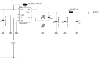
to take a small very very low power StepUp converter for the standyb mode ( able to make max. 100mA). If the 2AMps are required (we have an enable pin when 2AMps are required) put a "Boost StepUp (TPS61022) in parallel to the Low power stepUp.
to source the 2 AMps (see drawing attached)

Is this in general possible?
Which Very low Power StepUp can we choose (TPS61099?).
Can we do such parallel setting? what do we have to do to set the 2 TPS (61022 + ??) in parallel not to influence each other?

thanks

  • Hi Andreas,

    Before answering your question, firstly I want to explain the possibility for TPS61022 to operate from 0.7V~3Vin to 3.6Vout for below load profiles:

    (1)2A for 3s;

    (2)100mA for ?s (it is fine for TPS61022 at all conditions)

    (3)15uA in sleep mode (Always on)

    For above case, the most extreme case is 0.7Vin to 3.6Vout/2A. It needs at least 10.29A switch current limit in order to not protect the loads by shut down the LSFET.

    TPS61022 has minimum current limit spec of 6.5A, which means the device is not capable to pass the worst case. 

    For your question, TPS61022 and TPS61099 in parallel operation will definitely influence each other. In the worst case your would get full power coming from TPS61022.

    I have my below questions:

    What is your power source? Why would it has such a low VOUT? What is your load application? Is that NB-IoT? Please also note TPS61022 needs Vin to be initially 1.8V to successfully start up;

    Could you please clarify your quiescent current requirement? If you needs longer battery life time, then using TPS61022 for high power and TPS61099 for low power to save current consumption is ok. If you do not need it, then only TPS61022 is ok to use.

    TPS61094 is a very good bit if your load profile is lower. Just a reminder.

  • Answering your Questions:

    (2)100mA for ?s (it is fine for TPS61022 at all conditions)

    à 8s

    What is your power source?

    à Battery with min. 1,8V for get please the 0,7V – it was a type form my side. (we have already TPS61022 today in use)

    If you needs longer battery life time, then using TPS61022 for high power and TPS61099 for low power to save current consumption is ok

    • Yeah, that’s my question:so, can we combine the TPS61022 with the TPS61099 like in my attached drawing? What is need to be done, when for example TPS61022 is enabled (by enabled pin) and TPS61099 is also working:
      • Does TPS61022 influence TPS61099,when TPS61022 is NOT enabled. Do we have to add something that the combination is possible?
      • For the case both are enaböled (TPS61022+TPS61099..when modem is running), do we have to take care on something?
      • As remember: we want to combine the 2 blocks, because We want to make quiescent current as low as possible. TPS61099 has low quiescent current and TPS61022 is only responsible for the current peak of the Modem.
  • Hi Andreas,

    I think it is possible to parallel TPS61022 to TPS61099. When they are paralleled together, the one with lower impedance contributes higher current in heavy load. The frequency interface between each other can also generate beat frequency on VOUT. 

    Let me test this case and feedback to you later. Thanks!

    -Wenhao

  • okay, perfect, waiting for your test

    thanks

  • Hi Andreas,

    I have tested the case in your application. See the attached slides. Anymore questions please let me know. Thanks!

    -Wenhao

    Parallel Operation.pptx

  • Hi Wenhao,

    thas really great . thanks for the evaluation- we will take this product!

  • Hi Wenhao,

    just one question to get the summary:

    in this situation: TPS61022 is not enbaled and only TPS61099 is maintaining the VOut, what did you measured as quiesient current? How many uA?

  • Hi Andreas,

    If you need quiescent current test, please tell me your desired feedback resistors value for TPS61022 and your most concern use case (VIN, VOUT), i can tell test engineer to test this value for us. Thanks!

    -Wenhao

  • Hi Wenhou,

    see attached the TPS61022. In parallel there should be now TPS61099

    The worst case: VIN=1,2VDC  VOUT 3,8VDC

  • Hi Andreas,

    So I would let them to test the quiescent current for below case:

    (1)TPS61022 disabled, TPS61099 enabled;

    (2)TPS61022 same schematic as above;

    It suddenly reminds me of TPS61099's schematic on your side. Would you please also share it? Please note the tested value iwill be larger than what listed in datasheet because we measure the shut down current and assume VOUT=0V, but in your parallel operation VOUT is never 0V. Also the FB resistors are different from test.

    -Wenhao

  • Hi Andreas,

    Could you please comment above questions? It is meaningful to test IQ for both TPS61099 and TPS61022 because your system will use both of them.

    -Wenhao

  • Answer:
    Sory for being late, but i was on a short business trip. Okay. the topic is. we have not TPS61099 inserted yet (only TPS61022), because
    we want to know exactly this, how to put it in parallel. So pls recommend the best setting (around TPS61099) you can do, we will do
    this as first setUp.

  • Hi Wenhao,
    i do not fully understand your feedback:
    1) you already have your setUp with your evaluation kits. so you can measure the quiscient current in this setUp right?
    2) why: today we have only TPS61022 and NO TPS61099 conntec. so i have no circuit diagram and i suppose you give us a recommandation for this to achieve minimal quiecient current when mainting the VOUt
    by TPS61022 disabled and TPS61099 enabled

  • Hi Andreas,

    OK. Let me check this and give your the recommendation next week. Thanks!

    -Wenhao

  • Hi Andreas,

    I found TPS61022 with your configuration is unstable. It is mainly because of insufficient output capacitor. I see you have only use 2*10uF/10V. Considering DC bias effect this would derate 80% capacitance. This would make only about 4uF capacitance on output. I do not recommend the schematic like this. 

    For TPS61022, we should use more capacitor on VOUT to help increase PM and GM for your 2A in 3s. The performance of TPS61022 should be taken more care of because it is shut down in normal state;

    For TPS61099, use EVM configuration is recommended.

    Let me configure TPS61022 board with right COUT setting. Thanks!

    -Wenhao

  • Hi Wenhao, thnaks for first evaluation. So, only to be clear:

    1) On TPS61022 you will now configure correct COUT

    2) on TPS61099 you recommend setting according EVK

    you will configure 1)+2) and you will measure then quiescient current? to have final result.

    correct?

  • Hi Andreas,

    1) On TPS61022 you will now configure correct COUT

    Yes, the FB setting will be same as yours.

    2) on TPS61099 you recommend setting according EVK

    Yes, that is correct.

    you will configure 1)+2) and you will measure then quiescient current? to have final result.

    I will measure below cases:

    Case 1: TPS61022 enabled+TPS61099 enabled;

    Case 2: TPS61022 disabled+TPS61099 enabled;

    Case 3: TPS61022 enabled+TPS61099 disabled;

    Note in all of three cases above, TPS61099 and TPS61022 has been paralleled.

    -Wenhao

  • Hi Andreas,

    The test resource is very limited. I want to make sure the test would be do for several times.  Could you please confirm if you are ok with below configuration? Thanks!

    TPS61099: CIN: 10uF/25V/X5R/0603*1, COUT: 10uF/25V/X5R/0603*2; RFB_H is 1Meg, RFB_L is 390k, there is a 27pF cap parallel with RFB_H as loop compensator;

    TPS61022: CIN: 10uF/25V/X5R/0603*1, COUT: 10uF/25V/X5R/0603*3; RFB_H is 820k, RFB_L is 150k;

    -Wenhao

  • Hi Wenhou, 

    we doublechecked, yes this configuration would be absolut ok to check the quiescient current.

    thanks very much

  • Hi Andreas,

    Thanks for confirmation. Will give your results by this week.

    -Wenhao

  • Hi Andreas,

    See the test results below:

    We force TPS61022 VFB=0.7 and TPS61099 VFB=1.3V to ensure they both work at no switching state.

    TPS61022

    TPS61099

    Iq total (uA)

    VIN(V)

    Enable

    Enable

    27.1

    1.8

    Disable

    Enable

    3

    1.8

    Enable

    Disable

    26.7

    1.8

    -Wenhao