This thread has been locked.

If you have a related question, please click the "Ask a related question" button in the top right corner. The newly created question will be automatically linked to this question.

UCC28911: The maximum output current capability for HV Buck with UCC28911

Part Number: UCC28911
Other Parts Discussed in Thread: UCC28881

Hi teams

Customer is seeking a non-isolated HV buck solution with at least 15V/300mA (continuely) output level.

I noticed that UCC28911 and UCC28881 could use for such topology and we found several TIDA from TI.com.

However, these reference design output current is so small and can't meet cusotmer requirement.

I want to know are UCC28911 could support up the application up to 300mA? Thanks.

  • Hi Gabriel,

    May I ask what is the input voltage range of this design , such as minimum and maximum input voltage.

    Thanks.

  • Hi Jaden

    The voltage range is 85VAC~260VAC

  • Hi Gabriel,

    I have roughly calculated the switching frequency and inductance of the  output inductor. In theory , UCC28911 can support 300mA output current.  

    In BUCK configuration, the output current almost equal to the average current of inductor current . since UCC28911 is a DCM and QR controller . the peak current was limited to 700mA . so the power stage must running at CRM mode (turn on at first valley) to support a 300mA current(Maximum output current Iout ~= 700mA/2).  and there is also a maximum turn on time limitation in datasheet is 13us . customer have to carefully design the inductance to meet CRM operation during the full range of input voltage . and not exceed the maximum switching frequency . may be Lm = 1.5mH is a start point.

    Thanks.

  • Hi Gabriel,

    I correct the Lm to 370uH since the switching frequency have to higher than 44kHz  then the peak current can up to 700mA .

    The previous Lm = 1.5mH will results in a ~ 12kHz switching frequency.

    Thanks.

  • Jaden

    Thanks for your reply.

    I read a material in the past it indicate that the output current level will be limited by the Kcc( DEMAG*fsw constant). The conclusion is Ilimit/4.

    If it could support up to 300mA it will be great.  By the way, what will happen when output power is higer than 300mA? 

    I noticed that many other vendors HV buck is fixed switching frequecny, what difference will lead to if we select UCC28911 with AM/FM modulation for HV buck converter?

  • Hi Gabriel,

    UCC28911 is not special designed for HV buck, it's a flyback controller.  and it running at QR and DCM mode . the maximum peak current is 700mA . also there are minimum on time and maximum on time limitations . but for special designed HV buck controller , it can running at CCM mode . For buck topology , output current  should be 1/2 Ipeak multiply a coefficient that equal to Ton + Toff / Ttotal ,  in order to support 300mA output current . the Ttotal need to close to Ton +Toff , that means UCC28911 have to running at QR mode.  If output current exceed 300mA . it will trigger OCP protection.

    Thanks.

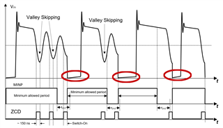
  • One more questions about valley switch mechnisam. Below diagram is capture from UCC28911 datasheet.

    Base on my understanding, when VDS drop nearby zero means MOSFET turn-on, and I marked three turn on cycle with red circle.

    I don't understand what the bottom axis indicated? It have couples pulse and marked with "switch on".

    The second questions is the minimum allowed period in below diagram is calulated base on control law output frequency information, am I right?

  • Hi Gabriel,

    When the MOSFET turn on . magnetizing current will gradually ramp up . it multiply the Rdson and current sense resistor equal to the voltage on Vds , that is why you see a gradually increasing voltage on Vds during MOSFET on time.

    Your understanding of second question is correct.

    Thanks. 

  • More questions about HV buck inductor design:

    Ton=[(Ipp*L)/(Vin-Vout)]

    Toff=[(Ipp*L)/(Vout)]

    Ton+Toff<(1/44Khz)

    Questions:

    1. Am my caluculation is right?
    2. As the minimum Ton time is 13us as you mention, we should made sure the L should be large enough to make the Ton>13us?
    3. As the AC line voltage range is wide, should I calculate base on minimum input voltage or maximum input voltage?
  • Hi Gabriel,

    To simplify the calculation, we ignored the 1/2 resonance time (it's also a part of switching cycle time). in this way, your calculation method is correct.

    13us is the maximum on time limitation. so the calculated L turn on time should be less than 13us.

    you have to use the minimum input voltage to calculate the L .  after you get the L value , you also have to verify if the on time is larger than tON(min)  at maximum input voltage . and if the switching frequency is below 115khz .

    That is all of limitations for your design.

    Thanks.