This thread has been locked.

If you have a related question, please click the "Ask a related question" button in the top right corner. The newly created question will be automatically linked to this question.

LM27403: LM27403 the delay of tracking function

Part Number: LM27403

Hi,

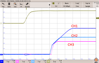
Test the tracking function of LM27403 to measure the following waveforms

Vin 12V, Vo set to 5V, load: 2A
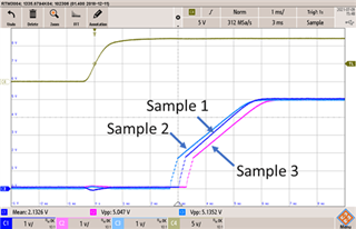
Startup time Sample 2 -> Sample 1 -> Sample 3


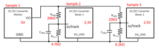
Take Sample 1 as the master, Sample 2 (3.3V), and Sample 3 (2.5V) as the slaver. As shown in the figure below,
During the test, it was found that Sample 3 would be a delay. Is there any error in the tracking function specification? thanks.

  •   

    The LM27403 imposes an Enable to Soft-Start delay that can vary slightly from part to part.  In this case, Sample 3 has a slightly longer Enable to Soft-Start delay than Sample 1.  Sample 2 may have a slightly shorter Enable to Soft-Start delay from Sample 1, so it is able to track Sample 1 immediately.

    If you want all three devices to start together, you can add a delay circuit to Sample 1, which is providing the tracking ramps for Sample 2 and Sample 3 so as to ensure Sample 1 is able to start it's soft-start last, after Sample 2 and 3 have completed their Enable to Soft-Start delays.

    If using a digital enable circuit to control the start-up, a simple R-C delay on the EN/UVLO of Sample 1 will typically suffice.

    If using the EN/UVLO as an analog UVLO, an R-C delay circuit and setting Sample 1 with a slightly higher DC threshold will provide a delay for both a quickly rising and a slowly rising input voltage.

  • Hi Peter,

    Thanks for your feedback.

    May I know the Soft-Start delay as shown in the datasheet?

    Where can I refer to the delay circuit (analog and digital), if I need all three devices to start at the same time? thanks,

  •  

    The Enable to Soft-Start delay is not specified in the datasheet, but is primarily driven by the time required to charge the VDD bypass capacitor, which is held discharged while the EN pin is held low in order to minimize leakage current in the disabled state. 

    The typical delay time with a 10μF bypass capacitor is 2ms with a +/- 20% tolerance.  One way to ensure all of the devices have started prior to enabling the 5V device providing the tracking ramps for the other devices would be to connect the 5V devices (Sample 1)'s EN/UVLO pin to the VDD output of one of the other devices. 

    To ensure Device 2 and Device 3 are enabled and ready prior to enabling Device 1, I recommend connecting Device 1's EN/UVLO pin to the VDD output of Device 2 with a 10kΩ / 10kΩ resistor divider.  This will ensure Device 2 and Device 3 have their VDD voltage at 2.3V prior to enabling Device 1.