This thread has been locked.

If you have a related question, please click the "Ask a related question" button in the top right corner. The newly created question will be automatically linked to this question.

TPS54231: Damaged after powering up from 24V

Part Number: TPS54231

Hi,

Issue: TPS54231 fail after powering up from 24V

We are using TPS54231DR in our design as step down converter with the following specifications,

VIN = 24V
VOUT = 5.5V
IOUT = 250 mA
We are powering the board from DC SMPS power supply.
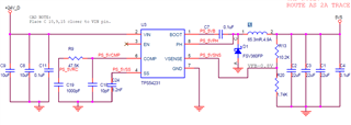
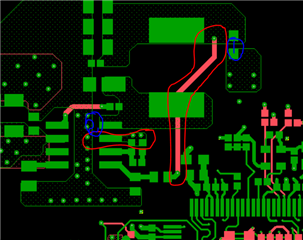
I am here with attaching the the image of schematics and layout of the particular section. 
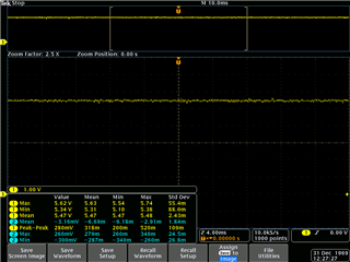
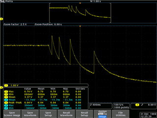
Also attaching the some wave forms.
I compared our design with reference design, and found some mismatches. They are listed below,
1.It is not recommended to draw the feedback line under the Inductor.
2.Connect the GND pin to a strong ground plane with multiple vias under or nearby the die. ,since it is the heat dissipating pin of the IC. we connected using only two     vias with the ground plane in other layers.
Are the above two reasons lead to the damage of the IC during its power up?
3. The inductor used in our schematic (IHLP3232DZER150M11) have DCR 61m.
4. The EN pin of the IC is in floating stage , so glitches are formed during power off.
wave forms
  • Hi, AS

    Some comments: 

    1. After IC is damaged, which pin is damaged? 

    2. What is failure rate? Does every board have issue? 

    3. I reviewed the schematic and layout, but I don't think the 2 reasons you mentioned will cause IC damaged. 

    4. Could you measure some waveforms on the good board? Including Vout, PH, and inductor current. 

    Test conditions includes power on/off and steady state. 

    BTW, What is tolerance of Vin?  

  • Hi Zhao,

    • The IC is damaged in two boards.
    • The pins 2(VIN), 6(COMP), 7(GND), 8(PH) are short in the IC after damage.
    • The resistance between Enable pin and shorted pins is 25R
    • The tolerance of the power supply is - Line Regulation : ≤0.01% +3mV

                                                                          - Load Regulation : ≤0.001% +3mV

                 I can submit the wave forms once I reached Lab.
    Thanks.

  • Hi, AS 

    From your description, IC is damaged heavily. 

    Could you take a picture of the damaged IC? are there any damages on appearance? 

  • Hi Zhao,

    There is no visual effects on the IC. Initially its powered on and worked fine. After some off and on cycle, it damaged. We regulated the input current at 200,mA.  Is there any possibility of a spike voltage?

    The IC maximum voltage is 28V.

  • Hi, AS 

    I suspect Vin is not very stable, could you double check if any spike voltage on Vin? 

    What is the inductor value? 

  • Hi Zhao,

    Actually the board is powered with a regulated SMPS DC power supply with current limited. Its voltage is stable.
    The inductor value is 15uH , tolerance is 20%, and DCR is 60m.

    With the IC damaged state , can we say possibility of short circuit in the output circuitry of the IC?

  • Hi, AS 

    1. After IC is damaged, please measure the impedance between Vout and GND.

    And unmount the TPS54231, measure again, then we can judge the short circuit happen at TPS54231 or at downstream circuit. 

    2. Could you measure some waveforms on the good board? Including Vout, PH, and inductor current. 

    Test conditions includes power on/off and steady state.