This thread has been locked.

If you have a related question, please click the "Ask a related question" button in the top right corner. The newly created question will be automatically linked to this question.

BQ2970: Series circuit with BQ29703

Part Number: BQ2970
Other Parts Discussed in Thread: BQ28Z610-R1, BQ40Z50, BQ4050

Hi,

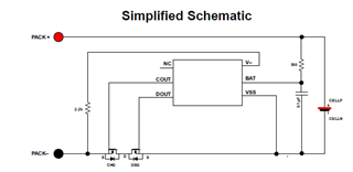
I want to power my device with two LiPo batteries in series and each cell should be protected by using a single BQ29703 circuit. So I have designed the following circuit:

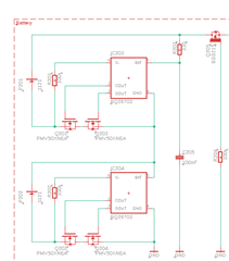
But I don´t have any idea if this circuit is working or if this circuit is correct. Can you please give me some feedback about this idea?

Thank you.

  • Hi Daniel,

    The BQ2970 is intended for a single cell.  VSS (or GND) should connect to the bottom of the cell such as shown in the data sheet simplified diagram.

    In your diagram if the FETs turn off for one device with a load the VSS will go above the BAT which will violate abs max and is likely to damage the part.  The standard circuit does not work well if stacked either since the V- pin would be pulled above the abs max of BAT + 0.3V.  If stacking the circuits the DOUT and COUT would need to be combined to a common FET control and the V- limited to safe ranges.  I don't know how practical this may be.  It may be simpler to use a gauge with protection such as the BQ28z610-R1, BQ4050, or BQ40z50.  See other options for 2 cells at www.ti.com/battery.  Gauges are more complex but multi-cell protectors commonly start with 3 cells.