This thread has been locked.

If you have a related question, please click the "Ask a related question" button in the top right corner. The newly created question will be automatically linked to this question.

BQ24715: How BQ24715 monitors discharge power consumption and system power consumption

Part Number: BQ24715

Hi Sir,

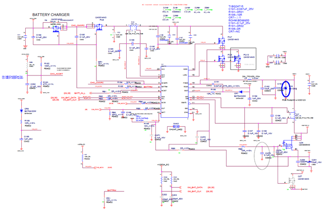
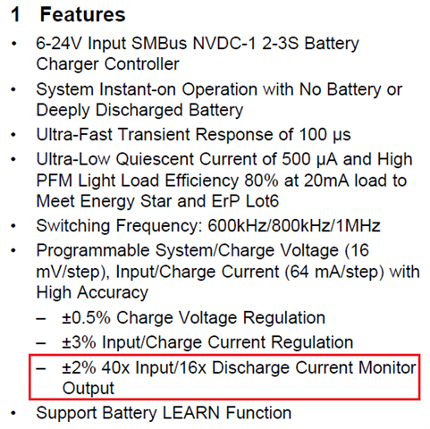
From the datasheet of BQ24715 I learned that it has discharge current monitor output function, so I was wondering how it monitor the discharge power consumption and system power consumption?

Thanks,

Best Regards

  • Hi,

       You can monitor IOUT as charge current or discharge current depending on bit set in ChargeOption() bit[4]. Refer to section 8.4.7 as well as register table description for ChargeOption().

  • Hi Kedar,

    Thanks a lot.

    But according to section 8.4.7 of the datasheet, we try to set the ChargerOption (0x12) to two values of 0x664E and 0x6646 and read the voltage of the IOUT pin (pin 7). The measured voltage values are as follows:

    1) Setting ChargerOption (0x12) to 0x664E, the voltage of IOUT pin is 0V.

    2) Setting ChargerOption (0x12) to 0x6646, the voltage of IOUT pin is about 0.2V.

    Can I know the cause of this problem? Or can u give some suggestion for this? 

    My diagram schematic is as follows:

    Thanks,

    Best Regards

  • Hi,

      I am looking into this and will respond by EOD

  • Hi Kedar,

    Is there any news for my question? 

    Now I have a new question, that is, considering the cost, we want to remove the n-channel power MOSFETs between adapter and BQ24715 (PQ5) in my schematic. I was wondering whether this is feasible?

    Thanks,

    Kind Regards

  • Hi Lumina,

       For IOUT questions you can refer to this post where a similar question was asked previously: https://e2e.ti.com/support/power-management-group/power-management/f/power-management-forum/921913/bq24715-adapter-current-battery-discharge-current-using-iout?tisearch=e2e-sitesearch&keymatch=BQ24715%2520IOUT#

    Yes, you can remove one of the NFET (the one whose body diode cathode is at the adapter). This helps control inrush current on adapter plug in, but is not essential. 

    The essential NFET required is the one whose body diode anode is at the adapter as this provides reverse voltage protection.

  • Hi Kedar,

    Thanks a lot, and now we have encountered a new problem with BQ24715. We use BQ24715 for notebook battery charging, and CW2015 for power metering. We found a problem when measuring battery discharge. The detailed problem description is as follows:

    1) When the battery power is in the range of 98%~100%, insert a 12V adapter, through the ammeter we can learned that it takes tens of seconds to several minutes for the battery to change from the discharged state to the charged state. But if using a 19V adapter, this conversion process can generally be completed within 10s.

    2) When the battery power is lower than 93%, the battery can be changed from the discharging state to the charging state within 10s when a 12V charger is inserted.

    So we want to know how the DPM of BQ24715 is turned on and off for the system power supply is mainly obtained from the adapter side or from the battery side, and how this is allocated.

    Thanks,

    Best Regards

  • Hi Lumina,

      The ammeter impedance in series interferes with the feedback loop and shouldn't be used to measure the charge current. You can simulate a battery with a bi directional sourcemeter. What is the charge regulation voltage?

    With regards to DPM, it is an input current regulation loop. The input current with a lower input voltage (12V vs 19V) is higher due to the physics behind step down converter. With higher duty cycle (VBAT increasing) the input current is higher. So it is possible that you are hitting the DPM loop. What is the DPM setting and measured input current?