This thread has been locked.

If you have a related question, please click the "Ask a related question" button in the top right corner. The newly created question will be automatically linked to this question.

TPS7A25: LDO ringing

Part Number: TPS7A25

Hi,

Good day.

Our customer is using the TPS7A25 and they have a ringing issue, kindly see below the description:

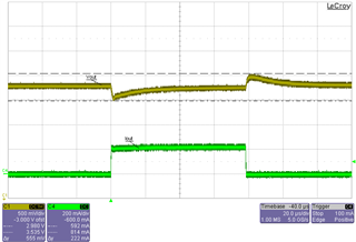
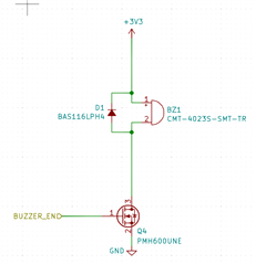
I am using two separate 3V3 fixed LDOs from the TPS7A25 series to generate two 3V3 rails - one is used by an nRF52 IC, RTC, other small ICs etc. The other is used by a magnetic buzzer and I am seeing ringing on this both input & output when this buzzer is used. However strangely it doesn't happen when it first turns on, but about 15us later.

What might be causing this ringing? It is relatively small on the 3V3, but on the input it is very large, 1V peak to peak which will cause problems for our circuit. What steps can be taken to reduce/eliminate this?

The input & output caps are both 2.2uF 0603 X7S 10% 25V by Murata. The buzzer is driven with a 4kHz PWM and takes about 160mA during the ON cycle.


Thank you for your help - this is for a smart lighting product soon to be introduced

Looking forward to your feedback. Thank you.


Regards,

Cedrick

  • Hi Cedrick,

    If I'm understanding this correctly, the ringing is a consequence of the inductive nature of the magnetic buzzer. I think it doesn't ring when the buzzer first turns on because the current is allowed to slowly climb but then when the current is turned off abruptly there is an inductive spike and subsequent ringing seen at the output of the TPS7A25 that couples to the input rail. 

    A good starting point would be to try adding more input capacitance. Using Murata's SimSurfing tool, I found a capacitor similar to the one that was used here and its capacitance at 12V DC bias is derated by about 65%, so the effective capacitance at the input is less than 1uF. If the customer can use a higher quality capacitor (e.g. a C0G dielectric capacitor) or add more capacitance I think the ringing could be reduced. Can you ask the customer to try a 10uF ceramic capacitor to see if that helps?

    Regards,

    Nick

  • Hi Nick,

    Thank you for your help.

    I've got a response from our customer, kindly see below:

    The buzzer stays on (3V3 applied across) throughout the ringing, so I didn't think it was that. I have uploaded the same oscilloscope capture again but this time with red arrows to show - first is where the buzzer FET turns on, the second is off.


    Possibly the current drops rapidly where the ringing occurs (3V3_BUZZ Channel4 rises quickly) - I haven't quite figured out why this occurs for a constant buzzer voltage, but nevertheless would like to understand the LDO behaviour.

    The key point is that it is not a plain dip (with *smooth* return) which would indicate stable operation but low capacitance. Rather it is ringing, which often points to resonance or instability. Increasing the capacitance may help, but could also mask the issue rather than solve the root. I thought there would be a cleverer way. Could it be stability? Other ideas? What methods might improve/test this specifically? E.g. I read low output ESR can cause (see TI SLVA115A).

    Also if it's something to do with the output / stability / capacitance I would have expected the largest effect at the output. The ringing at the input is about 20x higher than the output which I didn't expect. Not sure if that helps prompt ideas!


    Regards,

    Cedrick

  • Hi Cedrick,

    I think first we need to identify the source of the ringing. How is the +12V supply generated? The datasheet says that at 200kHz the TPS7A25 should have about 20dB of PSRR and the customer is seeing about 26dB. If the excitation was coming from the output of the LDO (i.e. from an inductive spike) the ringing would not be amplified back to the input but rather it would appear as a similar-magnitude ringing. It seems that the ringing might be originating from the 12V side. If that is the case then it would seem that the TPS7A25 is working correctly. 

    If the ringing is originating from the output side of the LDO then you could try a few easy things. Adding more input and output capacitance should help to improve PSRR and reduce the magnitude of the ringing. TPS7A25 is designed to be stable with low-ESR capacitors, so as long as you choose capacitors that have reasonably low ESR there should be no stability issues. You could also try using a ferrite bead at the input or output of the LDO that is driving the buzzer to help suppress the transient that is causing the ringing. 

    Regards,

    Nick

  • Hello Nick,

    Thank you for your response.

    I've just got a feedback from our customer regarding this;

    "Yes, that's a good suggestion about being sure of the source, and the PSRR, 20vs 26dB make sense, and it does make sense also that the input shouldn't be larger than the output ringing, part of what was confusing me so much. I had just assumed it was the output as I didn't see how the input could ring that much.

    The +12V is generated (for these plots, bench testing) from a TTi PL303 power supply, with ~40cm wires. I have tried using the remote sense and this doesn't have any effect. I have used this supply for many years and have always seen good clean behaviour.

    The +12V (in the real application) is from an LED Driver "VAUX" output, with 5-10cm wires. I did try it on this, but it is very fiddly to set up on comparison. I didn't get a scope capture unfortunately - I remember the ringing and oscilloscope being a vastly difference appearance, but that the peaks were about the same magnitude.

    How best to confirm the source is at the LDO input? What experiment would show this?

    Also, even in this case, why would the ringing be the opposite polarity at LDO input, to the output?"


    Regards,

    Cedrick

  • Hi Cedrick,

    Do you have a 12V battery that you could use to power your circuit? If you power it with a battery and you still see ringing then you can be sure that it is the LDO that is causing the ringing. It would also help if you can simplify the circuit, i.e. if possible isolate the buzzer and LDO. I'm not sure what the other connections look like, but if you had just the LDO, buzzer, and 12V battery then that would be a good way to separate what we think may be the issue from everything else in the system. If there is no ringing in this scenario, try supplying the circuit with the TTi PL303 supply and again check for ringing. 

    In your test setup do you have a way to capture the LDO output current to display it along with the voltages on the oscilloscope?

    I do not have an explanation for the phase inversion you are seeing from input to output - I had not noticed it until you pointed it out. LDOs do not add any inversion so this could be another clue. Let's see how the testing with a battery goes and we can revisit this phenomenon if we have to. 

    Regards,

    Nick

  • Hi Cedrick,

    I found a load transient scope shot for TPS7A25 with Vin = 10V, see below. You said the buzzer is taking about 160mA of current during the ON phase. I am seeing that the 3V3_BUZZ rail is drooping much more than I would expect since in this load transient shot of 0-200mA the output only droops by ~300mV. As I mentioned before, it would be nice to be able to see the LDO output current so we can see exactly what's going on.

    Regards,

    Nick

  • Hello Nick,

    Thank you for your continuous support.

    Kindly see the information provided by our customer below.

    "You're right, measuring current is needed - I was putting this off due to how immensely fiddly the mod would be, but I've bit the bullet!


    See attached plot - using a 0.5ohm resistor in the 3V3 buzzer LDO output path, measuring on either side with 2 scope probes and then using math functions to get current (M3 line).

    This shows a nice clean current rise. So still kind of confusing - the 3V3_BUZZ suddenly spikes upwards with no change in current, so I don't think it's a simple load transient. The best explanation I can think of is that the magnetic transducer armature suddenly reaches the end of its travel and back-drives 3V3_BUZZ so it rises sharply. Does this make sense to you?

    Maybe the LDO control loop then possibly overcompensates or does something strange and dips - but still not sure why it initially dips rather than rises? It looks like a voltage effect on the output rather than a normal current load transient (as both the input/output are stable during the initial current ramp).

    I'm also not sure why the 3V3_BUZZ doesn't recover to the full 3V3.

    I've also attached the same plot but run from a 12V lead acid battery instead, this suggests the second half of the ringing is a red herring and just due to the powersupply. However, the root issue is still there - the 12V dip and the magnitude is the same.


    Lastly, is there a Spice model available for this part?

    Thanks so much for your continued help! We're getting somewhere

    Regards,

    Cedrick

  • Hi Cedrick,

    Great! That looks a lot cleaner. 

    There are some features here that are a bit confusing. Why does the battery voltage droop? What is the current rating for the battery? I'm also not sure why the LDO and 12V lines do not recover once the current has reached its ON current until the switch is turned off. I guess the magnetic buzzer cannot be modeled like a simple inductor.

    I'm seeing the BUZZ_DRN voltage go from 3.3V to 0V when the switch is turned on. The 3.3V level makes sense before the switch is flipped, but I don't understand why its voltage would go to 0V. I would expect that the voltage would increase when the buzzer is activated. Is the BUZZ_DRN voltage measured at the far side from the LDO output? 

    Can you share a schematic or simplified diagram showing how the magnetic buzzer is connected? 

    Can you send me the magnetic buzzer part number? I want to take a look at it to see if it helps shed some light on what's happening. 

    Regards,

    Nick

  • Hi Nick,

    Good day. Kindly see below the response of our customer:

    The 12V battery is a large 12Ah. I'm pretty sure the 12V droop can't simply be the battery internal resistance, otherwise it would do it when the current first ramps up - instead it coincides with the sharp rise of the LDO output 3V3_BUZZ, likely due to some unknown buzzer effect and some unknown LDO behaviour in response.

    The BUZZ_DRN is the Drain of the FET (i.e. Q4 Pin3) which turns the buzzer on - when the FET turns on the drain goes to 0V. When it turns off, it goes above 3V3 as the current free-wheels through D1. I've attached a snippet of the buzzer drive circuit, which has the buzzer part # on.

    What LDO behaviour might explain the input dips in response to a sharp rise in output voltage, or with the output not returning to 3V3?

    Regards,

    Cedrick

  • Hi Nick,

    Another update:

    " I've tested replacing the regulators with the On Semi NCP718AMT250TBG to try and diagnose if it is the regulator behaviour (unfortunately only 2V5 part available). This appears to solve the issue - I get a dip on the 12V which is 10x less, and the output recovery is a lot smoother and closer to what it should be (although still doesn't reach the DC level it should for some reason).

    So I think it's looking like some regulator behaviour. Any ideas of what to try next?
    "

    Regards,
    Cedrick

  • Hi Cedrick,

    Hm.

    I agree that it is likely not the internal resistance of the battery causing the droop for the reason you gave.

    This behavior does not look like typical LDO behavior. Comparing to the load transient 'scope shot I posted above, I do not think the LDO can even respond with such a sharp edge. This to me implies that the buzzer if having a weird effect on it during operation.

    As I don't know exactly how this buzzer behaves, this may be a bad one, but I have an idea nonetheless. I wonder if the buzzer is dragging GND up with it. I.e. if the buzzer wants to have a voltage across it of less than 3.3V, if it has more I wonder if it drags GND up to compensate, which could explain the deviation in the 12V and 3.3V rails. If you think this is a reasonable idea, can you try putting a 6ohm (= 1V / 150mA) resistor between drain of the FET and the negative terminal of the buzzer to limit the voltage across the buzzer to 1V less than 3.3V at full load? I realize this might be difficult if it's on a board. If you had an adjustable version of TPS7A25 this could be tested with reducing the output voltage but I guess we're not that fortunate. 

    Regards,

    Nick

  • Hi Cedrick,

    Did the customer end up figuring out the issue or go with a different solution? I am curious about this one.

    Regards,

    Nick