Hi Sir,
This thread has been locked.
If you have a related question, please click the "Ask a related question" button in the top right corner. The newly created question will be automatically linked to this question.
Hi Users,
How does chip be soldered?
What is the output loading?
Can you capture the power on waveforms including VIN, Vout, SW and IL (If IL is not okay, taking Iout instead).
Thanks,
Lishuang
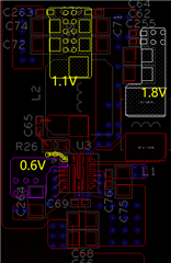
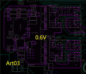
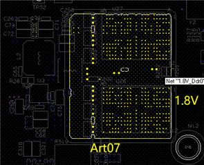
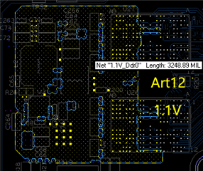
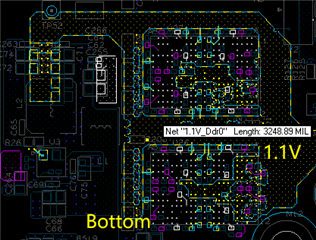
Please share your schematic and layout picture for review.
And what's your test condition? Vin/loading for each rails...
Yuchang
Hi Sir,
The VR is used to power LPDDR4X.
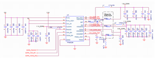
Schematic is is shown in the figure below,R765 Not Loaded.
BRD 14 Layers. Layer 2/4/6/9/11/13 is GND.
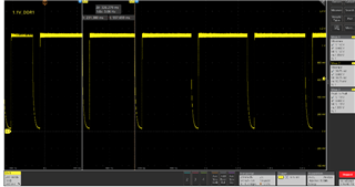
The voltage output waveform is shown in the figure below,
Hi,
Schematic looks well
Layout also seems ok, I just see BST line is a little narrow and I can't find Vsense line clearly, you may double check and make sure the line is away from the switching noise source.
Based on your design, if the loading is in proper range and soldering is good enough, OTP should not happen, suggest you check the loading value of each rail firstly? maybe you can check the inductor current to make it..., for LDO, maybe you can disable it to check if the IC work normally only with two buck rails.
Yuchang