This thread has been locked.

If you have a related question, please click the "Ask a related question" button in the top right corner. The newly created question will be automatically linked to this question.

BQ76942: Query regarding firmware development for BQ76942

Part Number: BQ76942
Other Parts Discussed in Thread: BQSTUDIO, EV2400

Hi Team,

May I ask for help? Kindly see our customer concern as stated below:

"We are developing a Battery Management System (BMS) for a 6s Li-ion battery pack intended to be used for light and medium weight aerial vehicles. For this we will be utilizing BQ76942 as the monitor. The following are some of the features we have considered while designing the BMS-
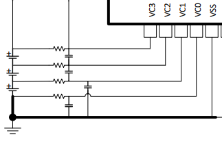
• Capability to monitor individual series cell voltages in real-time.
• External cell balancing nFET network for 120mA current.
• Internal REG of BQ76942 won’t be utilized to mitigate heating within IC. Voltage regulation will be done by separate buck converters.
• Parallel FET network to be separately implemented for charging(10-20A) and discharging(200A). These FETs will be externally controlled by MCU using CFETOFF and DFETOFF pins of BQ76942.
• Two 10K thermistors externally interfaces with BQ76942 for temperature logging of battery pack and FETs (pins TS1 and TS3).
• Current sensing will not be used.

Regarding the firmware part of BQ76942, we are intending to communicate and program using I2C. We have referred to the technical document provided and understood that read and write operations can be performed using a set of 7-bit commands and 16-bit subcommands. From the document its also clear that EV2400 (MSP430 MCU) and LaunchPad dev boards can act as MCU either by using a GUI (BQstudio) or a C program. In the “Software Development Guide” document, a python script is also shown as means to communicate with BQ76942.

Can you please recommend the most feasible way to use BQ76942 in our application? We are using Raspberry pi and Atmega 2560 MCU (chip form) in other subsystems of our drones. As explained above, the main purposes of BQ76942 for us are cell monitoring and balancing, temperature monitoring and FET control using an MCU. The thing we are stuck with is the MCU part and we hope to discuss this with you.
Are there relevant libraries available for atmega chips to operate BQ769x2 and has anyone used this family of BMS with Atmel-line of MCU before?

I’ll attach an image of the prototype BMS board we designed for better illustration. Hope to hear from you soon.
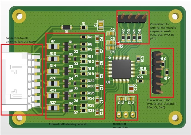
 "

I hope you can help us with this. Thank you so much in advance.

Kind regards,

Gerald

  • Hi Gerald,

    The most feasible option for this application is the proposed use of an MCU (with C code) to communicate with the BQ76942. The features proposed are also viable. Unfortunately, we have not worked with the atmega2560 mcu; however,  and I have been developing starter/example code for the STM32 mcu. I'm not suggesting to change MCUs, but I looked into i2c communication with the atmega2560, and it will take some modifications to our code to properly use. I would be happy to provide our code as well as work with the customer to explain the functionality and determine what should be adjusted to get their code working.

    Best regards,

    Andrew

  • Hi Andrew,

    Thank you for your response.

    Please be informed that I got a response from our customer as well. Please see below:

    "Sorry for the delay in response. I have read the response of your product team from the post. I would like to elaborate more in order to give your team a bit more clarity -
    •We had a constraint of using Atmega2560 because of the CAN system implemented in our system. But we can use another MCU for the BMS, and its choice needs to be made based on availability and ease to use and integrate. Could you please recommend some MCUs, preferably STM32 or TI?
    •We had initially planned to set the communication protocol of BMS as I2C, but because of unavailability of BQ76942 and BQ7694202 (I2C versions), we had to procure BQ7694201. To avoid the hassle of changing preconfigured settings, we will now use SPI as the mode of communication. Does the code that your team has developed for STM32 support SPI as well?
    And finally, we would also be happy to maybe have a discussion with your team. It would be helpful if we can explain the considerations made while designing the board and based on that your team will be able to understand and give recommendations in a better and convenient manner."

    Also I will inform our customer and check if he can directly email you.

    Thank you so much for your help.

    Kind regards,

    Gerald


  • Hi Gerald,

    Thanks for communicating with the customers.

    In terms of recommendations for MCU, I've found a few options below:

    There is the cheaper MCU solution such as the MSP430 line with the tradeoffs of no CAN capabilities: https://www.ti.com/microcontrollers-mcus-processors/microcontrollers/msp430-micrcontrollers/products.html 

    Certainly, there is a plethora of other options that may suit the customer so here is a link to the c2000 lineup of MCUs: https://www.ti.com/microcontrollers-mcus-processors/microcontrollers/c2000-real-time-control-mcus/products.html#o4=1

    Additionally, here is a reference design using a mcirocontroller with an external CAN controller. This could be useful if they need that feature.https://www.ti.com/tool/TIDEP-01014 

    We don't necessarily have capability on our end to port our starter code to every microcontroller, but the idea and functionality of our code should carry over to the different MCUs

    In terms of our code, we had started to work on converting it to be SPI capable. It is very similar to what we originally had, but we are still testing it. What we have should be a good starting point for the customer.

    Best,

    Andrew

  • Hi Andrew,

    Please be informed that I got few additonal question related to this concern. I hope you can further assist us. Below is the summary of our customer concern:

    "Can you take a note of two questions I couldn't find answers for from the datasheet -

    •Should VSS and VC0 (Most negative terminal of balance lead) be connected together possibly only by a single trace, or both need to left unconnected?

    •In our case, REGIN is receiving 5V regulated power from an external source and BREG is be connected to REGIN (as per the ‘Unused Pins’ section of the datasheet). Does a diode need to be connected [Anode to REGIN and Cathode to BREG] to ensure current does flow in the reverse direction (BREG to REGIN)?

    Apart from these questions, I don't have any queries since your comprehensive technical reference documents covered most of the parts of BQ76942."

    We will wait for your response. Thank you so much.

    Kind regards,

    Gerald

  • Hi Gerald,

    1) VC0 and VSS should be connected by an RC filter. An example can be found in the simplified schematic on page 1 of the datasheet or in Figure 16-1 and Figure 16-3. It is also important to note that VC0 has a lower voltage tolerance so VC0 needs to be connected through series resistor to VSS. This is to support the random cell connection if that may come up in manufacturing (more information on this can be found in section 16.3 of the datasheet, page 69 and 70). 

    2) For the case of REGIN and BREG, there is no requirement to have a diode between BREG and REGIN. If you are using an external supply for REGIN, the BREG pin won't be enabled (REG0_EN bit should be set to 0, this is the default parameter) so there won't be a current flowing from the BREG pin. 

    Hope this helps.

    Best Regards,

    Andrew