This thread has been locked.

If you have a related question, please click the "Ask a related question" button in the top right corner. The newly created question will be automatically linked to this question.

BQ25883: (BQ25881) Fault situation on STAT pin

Part Number: BQ25883
Other Parts Discussed in Thread: BQ25881
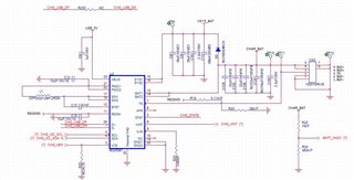
Hello TI experts,

my customer uses BQ25881 for their new product, they made DVT PCB for test.

here is some problems;

they made 100 PCBs, 3 of them do not working correctly.

- charging does not start after the power is on.

- STAT pin is blinking 1Hz period. <- i think this signal means fault status of charger.

- SW pin is different between normal IC and suspected IC.


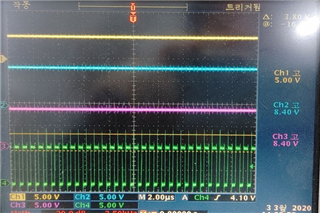
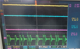
(the green is SW pin waveform ; left is normal IC, right is suspected IC)

yellow-VBUS, skyblue-VSYS, violet-VBAT

also V_REGN is little different. (normal; 5.00V / suspected; 8.1V)

now I only understand that the charger is under fault situation. could you give me some advice about this?

(they tested A-B-A swap test. the symptom follows the suspected IC.)

Best regards,

Chase

  • Hello Chase,

    Can you share the schematic and layout? If it is following the device I'm wondering if they were damaged somehow. A working IC put on a "bad" PCB will work correctly?

    Sincerely,

    Wyatt Keller

  • Dear Wyatt,

    Thank you for your reply.

    Here is the latest schematic and captured layout.

    (for your convenience, they use AC adapter - 5V, 2A / micro usb type b - for the input.)

    e2e_BQ25881_pcb.zip

    Yes, i strongly doubt that IC is damaged. they want to prevent it if the IC is damaged by something. so it will be very helpful which part of the IC is damaged.

    and working IC put on a "bad" PCB works correctly, "bad" IC put on a working PCB does not work. -> like i said they did ABA swap test.

    and how about ESD protection like TVS diode? would it affect to this failure? currently they use ferrite bead on the input.

    Best regards,

    Chase

  • Hello Chase,

    Thanks for sharing the files, I think since it is failing the ABA swap there must've been some damage to the charger, either ESD, temperature, or other physical damage. It looks like it is operating in PFM mode so it does look like it is somewhat operational still.

    The STAT pin will blink for one of the fault conditions: Charge suspend (Input over-voltage, TS fault, timer fault or battery over-voltage) OTG Buck Mode suspend (due to TS fault)

    Can you pull the register for VBUS_OVP, TS_STAT, BATOVP to confirm which one of the faults is occurring?

    Sincerely,

    Wyatt Keller

  • Dear Wyatt,

    here is the register values you requested ;

    - VBUS_OVP_STAT (REG_0E) : 0 (Normal)
    - VBUS_OVP_FLAG (REG_11) : 0 (Normal)
    - VBUS_OVP_MASK (REG_14) : 0 (VBUS_OVP rising edge produces INT pulse)
    - TS_STAT (REG_0D) : 5 (TS Cold)
    - BATOVP_STAT (REG_0E) : 0 (Normal)
    - BATOVP_FLAG (REG_11) : 0 (Normal)
    - BATOVP_MASK (REG_14) : 0 (BATOVP rising edge produces INT pulse)

    and here is other things ;

    1. 2 of defected IC is not working with I2C communication, the other one is working well.

    2. they used BQ25881 over 2 years ago. they used same schematic so far, artwork is a little different based on the product. and this high failure rate is first time for them.

    the main difference between this and before is the charging current (400mA to 650mA because the battery capacity increased 700mAh to 1000mAh)

    3. i think you already knew that this IC is MSL level 2 product. top marking is 0B8, so i think that it is much less than a year since they get this lot of product. Nevertheless is there any possibilities that not baking the product before SMT affect this failure issue?

    4. if the IC is damaged by ESD or something else, can we prevent damage with adding components like TVS diode?

    could you suggest about adding components to prevent ESD?

    (i.e. adding TVS diode on voltage input)

    cause the customer wants to modify their schematic if they really have to.

    Best regards,

    Chase

  • Dear Wyatt,

    Please let me know if there are any updates for the issue above.

    Thank you for your support.

    Best regards,

    Chase

  • Hello Chase,

    Can you share the 2 different PCB layouts so we can take a look? Are the schematics the same?

    Just changing the charging current shouldn't cause any affects like this.

    If the charger never works then it is possible it could be due to the SMT process if it's not heated correctly.

    Generally any external facing connection should have ESD protections on it. You can check section 7.2 ESD Ratings of the datasheet for the ESD rating of the IC. It would be good to locate if there is a possible source of ESD from testing before modifying the PCB for ESD.

    Sincerely,

    Wyatt Keller

  • Dear Wyatt,

    (This is updated thread, additional information added)

    Thank you for your reply.

    i attach the previous schematic and layout. please check it first.

    prev_sch.pdf

    prev_pcb.zip

    about SMT process, they follow JEDEC standard profile. so I think it is very clear that have no problem with SMT process.

    and here is one more question, actually I saw schottky diode in EVM schematic, also several not inserted diodes. what do you think which diodes are necessary, based on your mention?

    (# external facing connection should have ESD protections) they have only one external connection ; VBUS through micro USB connector (5V).

    and I think one of the reason is the voltage spike which is the moment of ac adapter first put on the VBUS pin. is it possible to get permanent damage because of voltage spike?

    please check these issues. Thanks.

    Best regards,

    Chase

  • Hello Chase,

    You can check the document in this other thread: https://e2e.ti.com/support/power-management-group/power-management/f/power-management-forum/849874/bq25883-bq25883-schematic-review

    Adding a TVS diode at the input may help with and ESD issues, I would recommend adding it if possible.

    You mentioned one device had I2C communication available still, what is the register dump on the damaged charger?

    Sincerely,

    Wyatt Keller

  • Dear Wyatt,

    Thank you for your support.

    customer now check and test many things to solve this issue. and they have some more questions.

    1. how about increase the value of capacitor of VBAT? they used 22uF before, and now they want to increase to 47uF or 68uF.

    is it better to prevent from ESD or other electric damage?

    2. they saw STAT pin blinking when they increased the value of capacitor to 47uF. is it normal operation?

    3. is it a possibility to get electrical damaged because of repeatedly attach-and-detach the battery to the VBAT pin?

    please check these issues. Thanks.

    Best regards,

    Chase

  • Hello Chase,

    1: They should be able to increase the capacitance on the BAT pin, just do not increase the capacitance too much so the slew rate is low on power up.

    2: STAT pin blinking indicates a fault, they should be able to read it from the registers for the specific fault.

    3: It should not cause damage to detach and reattach the battery multiple times.

    Sincerely,

    Wyatt Keller

  • Dear Wyatt,

    Thank you for your support.

    my customer said about another possibility, the battery which is out of warranty.

    they found another suspected device that is not charged, but they did not check that is the matter of charger or battery. and it has been over three years since the battery is made.

    (I think it is the problem of battery.)

    just they want to check all possibility, so is it possible to get charger damaged because of connection of this kind of battery?

    please check this issue. Thanks.

    Best regards,

    Chase

  • Hello Chase,

    An old battery shouldn't cause damage to the charger, it may cause the charger to behave differently if the batteries are really bad or old. That may be what is occurring in your original screenshots, if the internal resistance of the batteries is too high, the charger will not be able to charge with full current and will operate in PFM mode.

    If it is the battery, I don't know how the issue would follow the IC because of the ABA swap. Can you share the entire register dump while the charger is in the PFM state.

    Sincerely,

    Wyatt Keller

  • Dear Wyatt,

    I requested I-V curve trace to local TI office, i got a result today.

    they said that GND and pin19(REGN) is short and have current leakage.

    can it be one of the reason of this problem?

    and how can I prevent this problem? (like adding some component)

    please give me some advice. Thanks.

    Best regards,

    Chase

  • Hello Chase,

    If the REGN is shorted it is most likely a PCB issue, bad solder joint or other hardware issue. The best way is to find the issue and fix it on the boards.

    If REGN is shorted the converter will not operate, this is the main supply for the charger to run the gate drivers.

    Sincerely,

    Wyatt Keller