This thread has been locked.

If you have a related question, please click the "Ask a related question" button in the top right corner. The newly created question will be automatically linked to this question.

TL494: Differential output is not as expected

Part Number: TL494
Other Parts Discussed in Thread: ALLIGATOR

Hi E2E,

Please help our customer regarding their observation while using the TL494CN, here are the details:

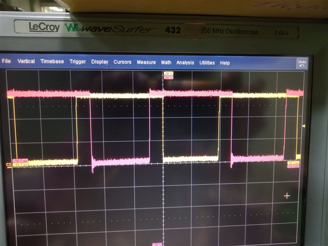
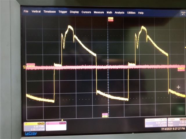
When I use the TL494CN in push-pull mode, the output from individual transistors (at collectors C1 and C2) w.r.t ground are as expected. The output looked ideal except for some disturbances due to using a worn-out DSO probe. But, in differential mode (voltage measured across the two collectors C1 and C2, excluding ground), the output voltage was not as expected. The operating frequency is 30kHz. Please help me understand why I'm facing this issue.
The first pic shows voltages at C1 and C2 w.r.t ground.

The second pic shows the voltage across C1 and C2.

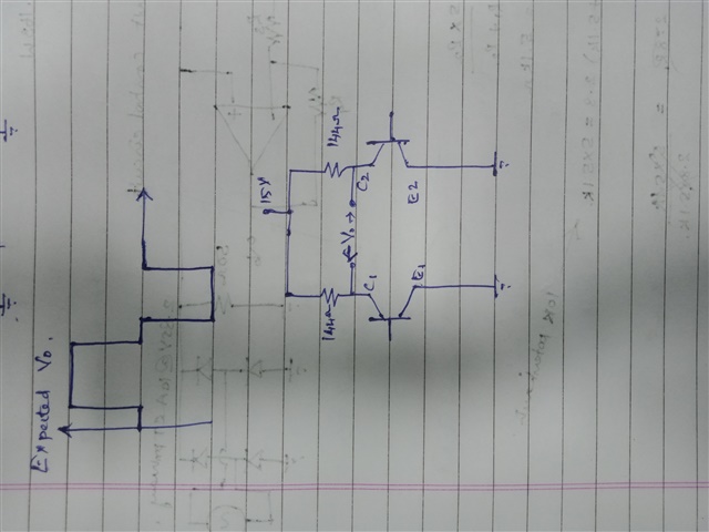
The third image shows the connections at the output of the TL494CN IC.

Thank you for the assistance.

Regards,
Carlo

  • Hello Carlo,

    The circuit you drew in image #3 is correct for push-pull mode (OUTPUT_CTRL = Vref).  This mode is shown as the common-emitter in the data sheet (figure 7).  So the outputs at C1 and C2 are as expected.  However, in single-ended or parallel mode (OUTPUT_CTRL = Ground) the output transistors are in an emitter-follower configuration.  These 2 modes of operation are shown on page 9, figures 7 and 8.  Figure 9 in the data sheet shows an example of parallel mode.

  • Hello Eric,

    According to our customer, it is correct that the outputs would be different in "push-pull" and "parallel" modes which can be configured using the "CONTROL" pin. But they didn't change the mode and the mode used was "push-pull" only. The issue is that, in push-pull mode, the outputs at the individual collectors (with reference to Ground) are as expected and that between two collectors looks so different from what is expected, as shown in the waveforms.
    The customer is not using the "Parallel" mode. Your help is appreciated.

    If you need other information, please let me know so I can request it from our customer.
    Regards,
    Carlo

  • OK.  "Differential mode" confused me a bit.  Thanks for the clarification.

    How did he make the differential measurement?  With a single probe and ground lead ('scope floating?), or a differential probe between the 2 collectors? 

  • Hello Eric,

    The customer had connected a single probe, with ground at one collector and probe at the other collector.

    Regards,
    Carlo

  • Hi Carlo,

    The differential response cannot be measured with one of the collector outputs grounded by the 'scope (alligator clip).  There are two methods that he could use:

    1) Connect two single-ended probes from C1 to ground and C2 to ground, as he did previously.  Then, use the MATH function in the 'scope to generate a third trace of Ch1 minus Ch2.

    2) Use a true differential probe, such as the ZD200 from LeCroy (or equivalent) connected between C1 and C2.

    If the customer uses either of these methods they should obtain the expected waveform.

    Eric