Hi,
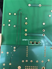
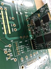
When I have received my PCB from manufacture, the PCB footprint for the half bridge GaN demonstration board is not correct. Or at least, the one I created, is not correct.
I have attached some images to support this question.
The issue is that the high current connectors do not fit into my PCB when they are inserted into the Milli-Max connectors. However, if I do not use the Milli-Max connectors, and insert the high current pins straight into my PCB, they do (just about) fit. I am worried about two things:
Mechanical strength: I do not want to snap the high current pins of the half-bridge board. I can insert them in so far before I get worried that they may snap.
Soldering: Without the actual Mili-max connectors inserted into the board, and just the pins inserted, there is obviously a larger hole left in the PCB.
Is it okay to solder the pins directly into my PCB without the connectors, will they still conduct appropriately? This is just a prototype, so although it would be nice to be able to remove the demonstration boards, it is not essential.
To connect them to the board directly, should I just use plenty of solder to fill the holes?
Is there any other alternate way I can connect the demonstration board to avoid damage and this small design error? I'd rather not completely redesign my PCB board.
Regards,
Joel